A rubber ball cleaning system

A cleaning system and technology for rubber balls, applied in the field of rubber ball cleaning systems, can solve the problems of low ball collection rate, staying in, and high equipment failure rate, and achieve the effects of uniform cleaning effect, long rubber ball life and high operating efficiency.

Active Publication Date: 2017-07-21
北京华亿宏图机电设备有限公司
View PDF8 Cites 0 Cited by
  • Summary
  • Abstract
  • Description
  • Claims
  • Application Information

AI Technical Summary

Problems solved by technology

7-13% of the rubber balls are put in each time, and the number of rubber balls entering the condenser with the water flow is about 3% each time, and the cleaning effect is not uniform
The cleaning effect of the cooling tube located in the middle of the condenser is good, and the effect of other parts is not ideal, which is the main reason affecting the cleanliness of the condenser
When collecting the ball, the rubber balls often gather near the ball collecting port of the ball collecting device, and the ball collecting rate is low
Especially in winter, the water volume of the circulating water decreases, resulting in a decrease in the water flow velocity in the condenser, and the rubber balls often stay in the cooling pipe of the condenser, or float on the upper end of the ball collector, resulting in a large number of rubber balls that cannot be recovered for a long time
[0006] Some new types of rubber ball cleaning systems, such as those powered by compressed air, have complex structures, too many valves and too many switches per work, and the equipment failure rate is high
Since compressed air needs to be separated from air and water, it is also difficult to achieve a 100% serve in this way
Some new rubber ball systems use the way that the rubber balls do not pass through the water pump, and the water pump has high efficiency, but because the water pump needs to start from zero speed
Cleaning is not optimal

Method used


Image

  • A rubber ball cleaning system
  • A rubber ball cleaning system
  • A rubber ball cleaning system

Examples


Embodiment Construction

[0064] Specific embodiments of the present invention will be described in detail below.

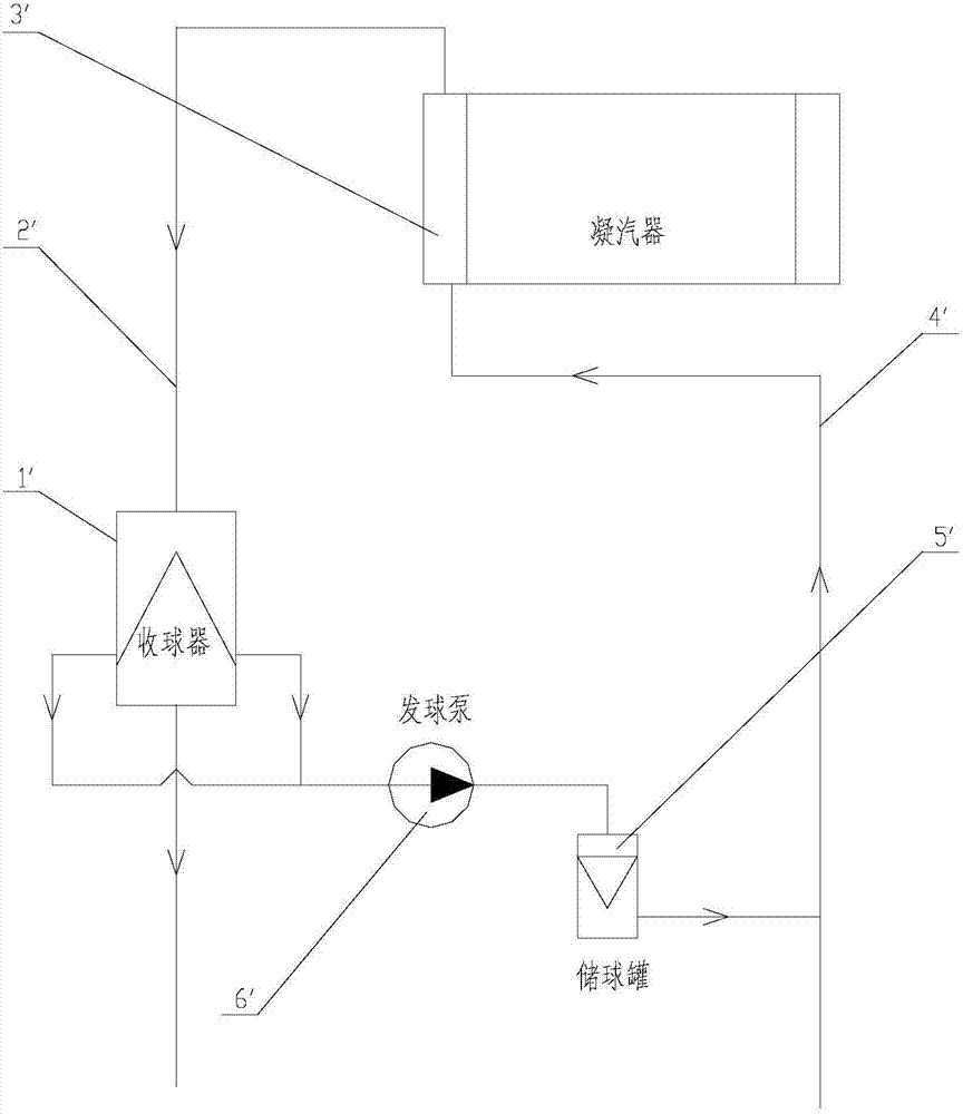
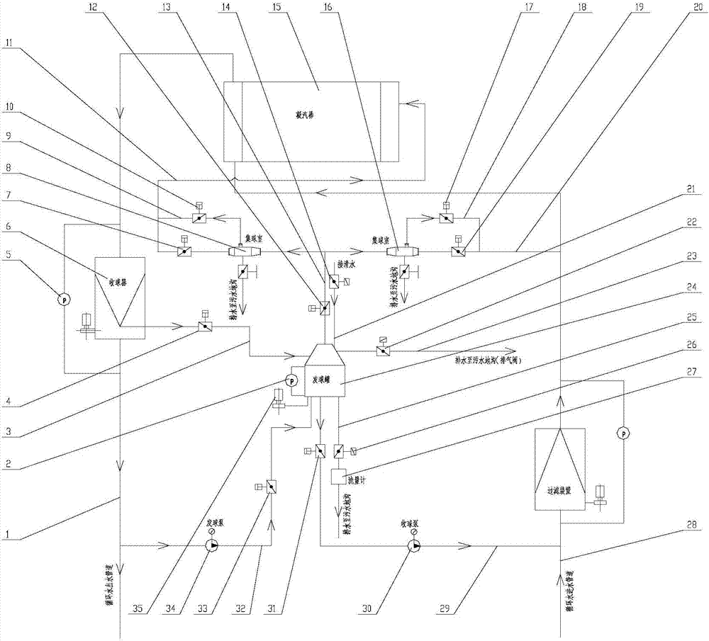
[0065] Such as Figure 1~3 Shown, a kind of rubber ball cleaning system comprises ball collecting device 6, ball sending device 24, second ball collecting device 8 and first ball collecting device 16 and controller,

[0066] The ball server 24 is connected to the ball outlet of the ball collector 6 through the ball collection pipeline 3, and the ball collection valve 4 is arranged in the ball collection pipeline 3,

[0067] The ball server 24 is respectively connected to the first ball collector 16 and the second ball collector 8 through the third ball collector 13, and the third ball collector 13 is provided with a third ball collector 12,

[0068] The ball server 24 is connected to the ball pump 34 through the second water outlet pipeline 32, the second water outlet pipeline 32 is provided with a water outlet valve 33, and the ball server pump 34 is externally connected to the circulat...


PUM


Abstract

The invention relates to a rubber ball cleaning system which comprises a ball receiving device, a ball serving ball, a second ball collecting device, a first ball collecting device and a controller. The ball serving device is connected with a ball outlet of the ball receiving device. The ball serving device is connected with the first ball collecting device and the second ball collecting device. The ball serving device is connected with a ball serving pump. The ball serving device is connected with an inlet of the ball receiving pump, the ball serving device is externally connected with a clean water pipeline, a flow pipeline and an exhaust pipeline, the first ball collecting device is connected with a circulating water inlet pipeline, the second ball collecting device is connected with a water chamber of a condenser, the circulating water inlet pipeline is connected with the water chamber of the condenser, and a dehydration motor is in transmission connection with the ball serving device. The controller is connected with a first pressure difference sensor, a ball receiving valve, a second pressure difference sensor, a second ball serving valve, a second drainage valve, a third ball serving valve, a clean water valve, a first drainage valve, a first ball serving valve, an exhaust valve, a flow valve, a flow meter, a ball receiving pump, a water inlet valve, a water outlet valve, the ball serving pump and the dehydration motor.

Description

technical field [0001] The invention belongs to the field of mechatronics, and in particular relates to a rubber ball cleaning system. Background technique [0002] The rubber ball cleaning system is a widely used device for online cleaning of condenser cooling pipes in the working process. [0003] Traditional rubber ball cleaning equipment such as figure 1 As shown, the working process includes a cleaning process and a ball collecting process. The soaked rubber balls are thrown into the ball storage tank (5'), and the number of the balls thrown is 7-13% of the number of cooling water pipes on one side of the condenser with one flow. Start the ball pump (6'), and the rubber balls are sent from the ball storage tank (5') to the circulating water inlet pipe (4') of the condenser (3'). Driven by the circulating water flow, the rubber ball enters the cooling pipe of the condenser. After wiping the cooling pipe, the rubber ball enters the circulating water outlet pipe (2') wi...

Claims


Application Information

Patent Timeline
Patent Type & Authority Patents(China)
IPC IPC(8): F28G1/12F28G15/00
CPCF28G1/12F28G15/00F28G15/003
Inventor 梅玉强王容强梅玉伟姚军营戚永鹏林学明田月根赵越
Owner 北京华亿宏图机电设备有限公司
Why Eureka
Try Eureka