Soil body two-dimensional fracture testing method and device
A technology of fracture test and test device, which is applied in the direction of testing material strength by applying stable shear force and testing material strength by applying stable tension/compression, which can solve the problem of obtaining continuous distribution characteristics of compressive shear combined force and soil sample strain and critical stress relationship, comparative study of inconvenient fracture problems, etc.
- Summary
- Abstract
- Description
- Claims
- Application Information
AI Technical Summary
Problems solved by technology
Method used
Image
Examples
Embodiment 1
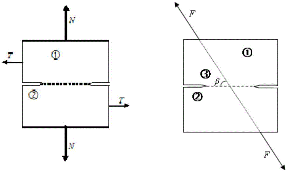
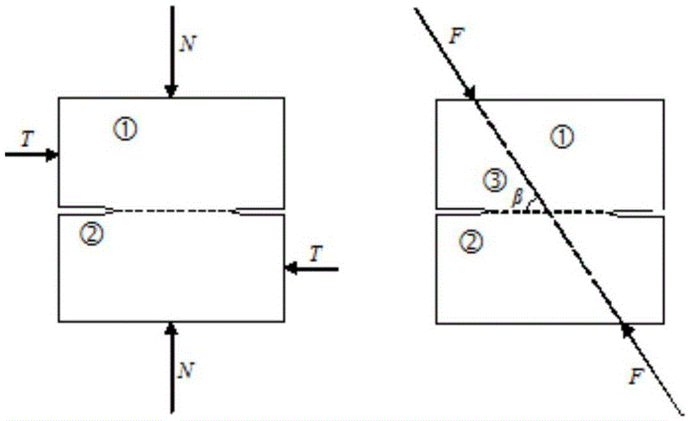
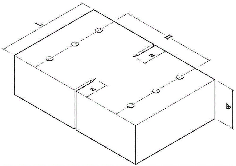
[0051] The test device includes a sample, a loading plate I1 and a loading plate II2. The loading plate I1 and the loading plate II2 are identical loading plates, and together constitute a loading fixture. The installation of the test device, the test is fixed by the pin through the sample fixing hole I1-4 and the sample fixing hole II2-4 respectively with the sample holding plate I1-5 and the sample holding plate II2-5 On the loading plate, the loading rod I1-7 and the loading rod II2-7 are respectively fixed on the loading rod installation hole I1-2 and the loading rod installation hole II2-2. The other ends of the loading rod I1-7 and the loading rod II2-7 are respectively connected to the external loading power device, and the loading rod I1-7 and the loading rod II2-7 are always kept on the same straight line. The start-up, loading mode, loading rate and termination operation of loading rod I1-7 and loading rod II2-7 are all controlled by computer control and data acquis...
Embodiment 2
[0063] The test device includes a sample, a loading plate I1 and a loading plate II2. The loading plate I1 and the loading plate II2 are identical loading plates, and together constitute a loading fixture. The installation of the test device, the test is fixed by the pin through the sample fixing hole I1-4 and the sample fixing hole II2-4 respectively with the sample holding plate I1-5 and the sample holding plate II2-5 On the loading plate, the loading rod I1-7 and the loading rod II2-7 are respectively fixed on the loading rod installation hole I1-2 and the loading rod installation hole II2-2. The other ends of the loading rod I1-7 and the loading rod II2-7 are respectively connected to the external loading power device, and the loading rod I1-7 and the loading rod II2-7 are always kept on the same straight line. The start-up, loading mode, loading rate and termination operation of loading rod I1-7 and loading rod II2-7 are all controlled by computer control and data acquis...
Embodiment 3
[0075] The test device includes a sample, a loading plate I1 and a loading plate II2. The loading plate I1 and the loading plate II2 are identical loading plates, and together constitute a loading fixture. The installation of the test device, the test is fixed by the pin through the sample fixing hole I1-4 and the sample fixing hole II2-4 respectively with the sample holding plate I1-5 and the sample holding plate II2-5 On the loading plate, the loading rod I1-7 and the loading rod II2-7 are respectively fixed on the loading rod installation hole I1-2 and the loading rod installation hole II2-2. The other ends of the loading rod I1-7 and the loading rod II2-7 are respectively connected to the external loading power device, and the loading rod I1-7 and the loading rod II2-7 are always kept on the same straight line. The start-up, loading mode, loading rate and termination operation of loading rod I1-7 and loading rod II2-7 are all controlled by computer control and data acquis...
PUM
 Abstract
Description
Claims
Application Information
 - R&D
- Intellectual Property
- Life Sciences
- Materials
- Tech Scout
- Unparalleled Data Quality
- Higher Quality Content
- 60% Fewer Hallucinations
Browse by: Latest US Patents, China's latest patents, Technical Efficacy Thesaurus, Application Domain, Technology Topic, Popular Technical Reports.
© 2025 PatSnap. All rights reserved.Legal|Privacy policy|Modern Slavery Act Transparency Statement|Sitemap|About US| Contact US: help@patsnap.com


