
Optical fiber cutter with bilateral cutting function

A kind of optical fiber cutter, double-sided technology, applied in the coupling of optical waveguide, etc., can solve the problems of easy damage to the end face of optical fiber, cumbersome operation, low efficiency, etc., and achieve the effect of reducing the probability of damage, reducing operation steps, and easy operation

Active Publication Date: 2016-04-13
NANJING JILONG OPTICAL COMM
View PDF5 Cites 2 Cited by
  • Summary
  • Abstract
  • Description
  • Claims
  • Application Information

AI Technical Summary

Problems solved by technology

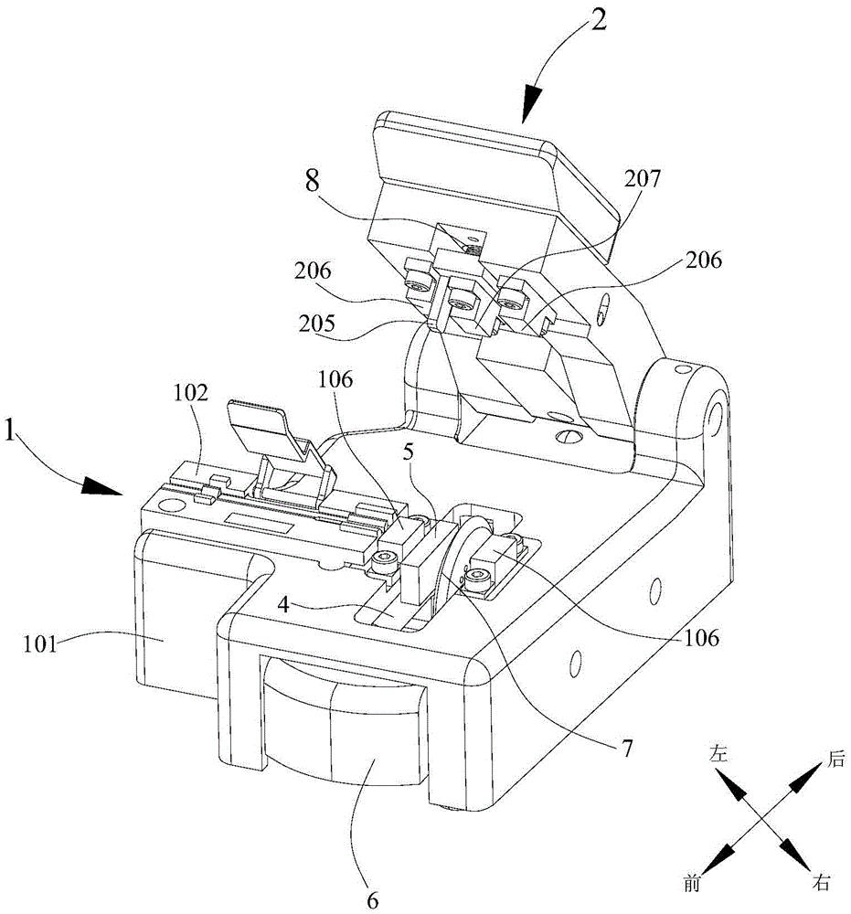
[0004] This kind of fiber cutter can only cut on one side, and the efficiency is not high; and this kind of fiber cutter puts the fiber holder on the left side of the cutter, and when placing the right side of the fusion splicer, you need to use your left hand to cut The optical fiber is removed from the optical fiber holder, handed over to the right hand, and then placed on the right side of the fusion splicer by the right hand. The operation is cumbersome and the end face of the optical fiber is easy to be damaged.

Method used


Image

  • Optical fiber cutter with bilateral cutting function
  • Optical fiber cutter with bilateral cutting function

Examples


Embodiment Construction

[0013] The present invention will be further described below in conjunction with the accompanying drawings and specific embodiments.

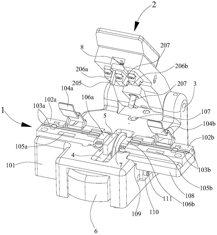
[0014] Fiber cleavers that cut on both sides, such as figure 2 As shown, it includes a main body 1 and a cover body 2 , and the cover body 2 is hinged on the rear side of the main body 1 through a hinge 3 in an openable and closable manner. The main body 1 includes a base 101, a left fiber holder 102a, a right fiber holder 102b, a left lower holder 106a, a right lower holder 106b, and a cutter. The base 101 has a substantially F-shaped section, consisting of an upper surface, The left side wall and the right side wall are integrally formed. The base 101 has a rectangular opening 4 on the right side. The rectangular opening 4 is located between the left side wall and the right side wall. The upper surface of the base 101 has a limit groove 109 on the right side, and the mounting platform 108 is stuck in the limiting groove 109. The lower part ...


PUM


Abstract

The invention relates to an optical fiber cutter with a bilateral cutting function. The optical fiber cutter comprises a main body and a cover body; the cover body is connected with the rear side of the main body in a unfoldable and foldable manner; the main body comprises a base, optical fiber clamping components, a cutter and one pair of lower clamping devices; an opening is formed in the base; the lower clamping devices are symmetrically fixed to the left side and right side of the opening; the optical fiber clamping components comprise a left optical fiber clamping component and a right optical fiber clamping component; the left optical fiber clamping component is fixed on the upper surface of the base and is located at the left side of a corresponding lower clamping device; a carrier stage is fixed to the right side wall of the base; the right optical fiber clamping component is fixed to the upper surface of the carrier stage; the left optical fiber clamping component and the right optical fiber clamping component are symmetrically fixed to the left side and right side of the opening; the cutter comprises a cutter frame and a circular blade; the cutter frame is located in the space of the lower part of the base; the circular blade is attached on the cutter frame; one part of the circular blade protrudes upwards from the opening; and the circular blade can move back and forth in the opening. With the optical fiber cutter of the invention adopted, bilateral cutting can be realized, operation steps can be reduced, collision probability can be reduced, and cutting efficiency can be improved.

Description

technical field [0001] The invention relates to an optical fiber cutter for cutting optical fibers, in particular to a double-sided optical fiber cutter. technical background [0002] Optical fiber is an important part of the optical communication system, which provides a channel for optical signal transmission. With the wide application of optical fiber in communication, a large number of optical fiber cables have been laid today. However, optical fiber cables are often damaged by man-made or natural disasters and need to be repaired. The cutting position needs to be very precise and the cutting surface needs to be flat, otherwise the optical fiber will scatter after being fused by the optical fiber fusion splicer. [0003] Existing fiber cutters such as figure 1 As shown, it includes a main body 1 and a cover body 2 , and the cover body 2 is openably and closably connected to the back side of the main body 1 . The main body 1 includes a base 101 with a rectangular openi...

Claims


Application Information

Patent Timeline
Patent Type & Authority Applications(China)
IPC IPC(8): G02B6/25
CPCG02B6/25
Inventor 刘斌
Owner NANJING JILONG OPTICAL COMM
Learn More