
Passive unbalance treatment module structure

A modular structure, balanced technology, applied in the direction of reducing the asymmetry of the polyphase network, eliminating/reducing the asymmetry of the polyphase network, the board/panel/desk of the substation/switchgear, etc., can solve the three-phase current in the power system. Balance, short service life of electronic components, insufficient IGBT stability, etc., to achieve the effect of less installation process, low manufacturing cost, quick and convenient after-sales and maintenance

Active Publication Date: 2016-04-13
GUANGDONG GUANGDA ELECTRICAL
View PDF7 Cites 0 Cited by
  • Summary
  • Abstract
  • Description
  • Claims
  • Application Information

AI Technical Summary

Problems solved by technology

[0002] With the continuous growth of my country's economy, the electricity load has increased rapidly, and the user's electricity demand has also increased significantly. This has brought more serious problems to my country's power grid, which is already short of electricity: the three-phase current in the power system of the distribution network Balance has strict requirements; the number of loads in the distribution network is increasing, and they are connected to the power system without detailed layout and distribution, resulting in an unbalanced three-phase current in the power system, which requires imbalance management The module can solve this situation and meet the needs of the distribution network
[0003] However, a large number of active imbalance management modules have begun to emerge. Although it solves the problem of current imbalance in the power system, the problems of the active imbalance management module also follow, so there are still many shortcomings as follows : (1) The active passive unbalance control module uses IGBT thyristors, which are relatively expensive to purchase; (2) The stability of the IGBT is insufficient and easily damaged; (3) Other electronic components installed inside (4) The module has high temperature requirements for the installation environment; (5) The installation capacity is single, and multiple modules are used in combination, which occupies a large space; (6) There are many components and assembly steps inside the module , resulting in difficult installation, requiring professional guidance and operation; (7) When a module fails, it is difficult to overhaul on-site due to the large number of components; (8) When the module needs to replace components, it is inconvenient to disassemble; (9) Module detection The point is hidden, and the shell needs to be disassembled to detect; (10) Operation and debugging require professional knowledge personnel, and casual operation is easy to damage the module
[0004] There are many problems mentioned above in the existing active imbalance management module, which cause unnecessary losses to the user. Therefore, the above problems can be solved for the passive imbalance management module

Method used


Image

  • Passive unbalance treatment module structure
  • Passive unbalance treatment module structure
  • Passive unbalance treatment module structure

Examples


Embodiment Construction

[0034] The present invention will be further described below in conjunction with the accompanying drawings and embodiments.

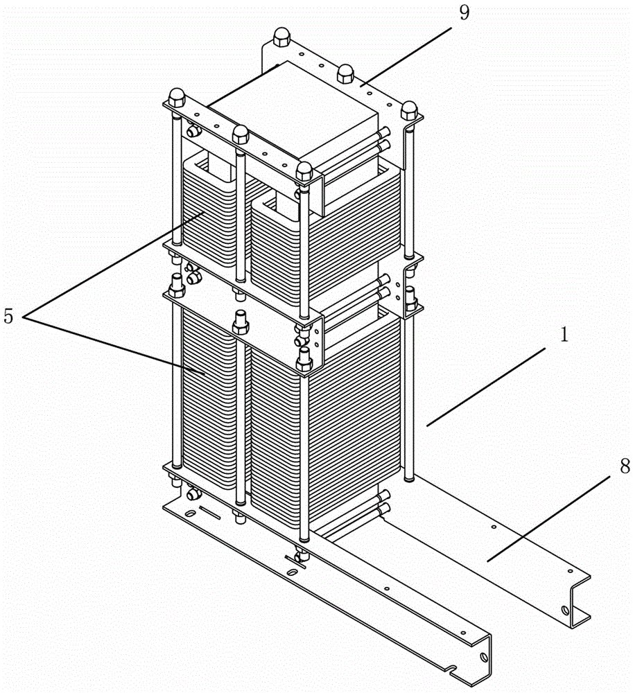
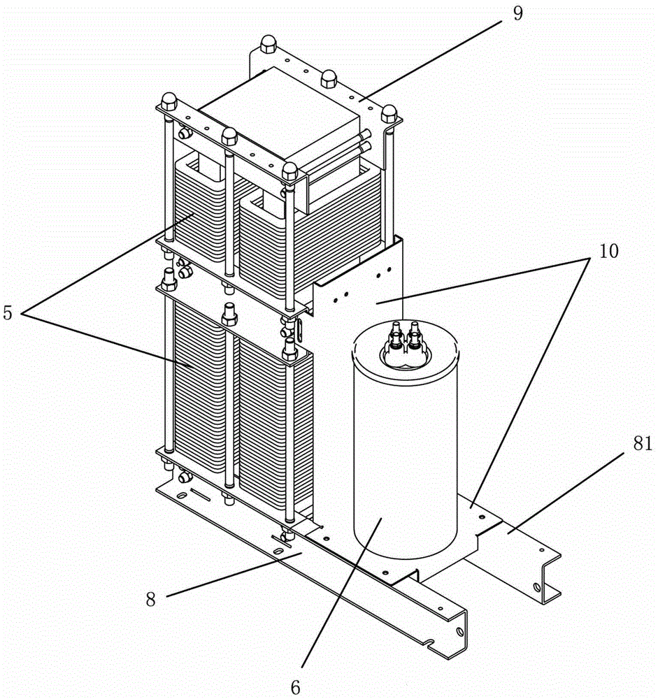
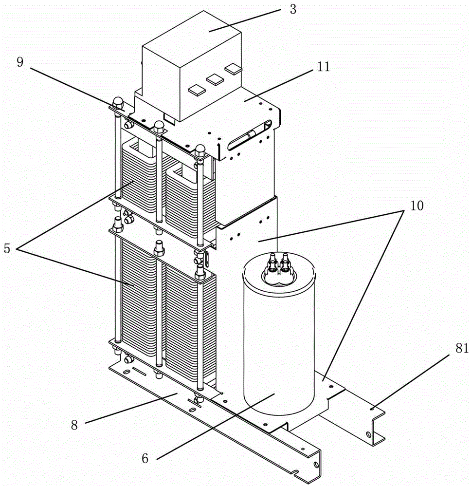
[0035] see Figure 1 to Figure 6 As shown, the structure of the passive unbalance control module includes a mounting frame 1, a knife fuse switch 2, a vacuum contactor 3, a control board 4, a reactor 5, a capacitor 6 and a connecting terminal 7, wherein the mounting frame includes Fixed steel channel 8 and angle steel 9, the fixed steel channel 8 is on the bottom, the angle steel 9 is on the top, the capacitor 6 and the reactor 5 are installed on the fixed channel steel 8 together, the knife melting switch 2, the vacuum contactor 3, and the control board 4 are all Installed on the angle steel, the knife melting switch 2, the vacuum contactor 3, the control board 4, the reactor 5, the capacitor 6 and the connecting terminal 7 are connected in series.

[0036] See figure 1 As shown, as a part of the patented passive unbalance control module structure of...


PUM


Abstract

The invention relates to a passive unbalance treatment module structure comprising a mounting rack, a fuse switch, a vacuum contactor, a control panel, electric reactors, a capacitor and connecting terminals. The passive unbalance treatment module structure is characterized in that the mounting rack comprises a fixed steel tank and angle steel, wherein the fixed steel tank is arranged at the lower part and angle steel is arranged at the upper part. The capacitor and the electric reactors are installed on the fixed steel tank together. The fuse switch, the vacuum contactor and the control panel are installed on angle steel. The fuse switch, the vacuum contactor, the control panel, the electric reactors, the capacitor and the connecting terminals are connected in series. The passive unbalance treatment module structure has advantages of being more stable, small in size, simple in components and parts, wide in application range and convenient to maintain. Compared with conventional active and passive unbalance treatment module, the module is more reliable and more stable and has higher cost performance.

Description

technical field [0001] The invention relates to a passive imbalance control module structure, in particular to the further improvement of the active imbalance control module. Background technique [0002] With the continuous growth of my country's economy, the electricity load has increased rapidly, and the user's electricity demand has also increased significantly. This has brought more serious problems to my country's power grid, which is already short of electricity: the three-phase current in the power system of the distribution network Balance has strict requirements; the number of loads in the distribution network is increasing, and they are connected to the power system without detailed layout and distribution, resulting in an unbalanced three-phase current in the power system, which requires imbalance management The module can solve this situation and meet the needs of the distribution network. [0003] However, a large number of active imbalance management modules ha...

Claims


Application Information

Patent Timeline
Patent Type & Authority Applications(China)
IPC IPC(8): H02B1/04H02J3/26
CPCY02E40/50H02B1/04H02J3/26
Inventor 吴文志吴军营欧阳乾赞吴景营
Owner GUANGDONG GUANGDA ELECTRICAL
Learn More