
Buried cable laying device

A cable laying and vehicle frame technology, which is applied in the field of direct buried cable laying devices, can solve the problems of low construction efficiency, large human resource occupation, and heavy workload of construction personnel, and achieve the effect of reducing workload and improving construction efficiency

Inactive Publication Date: 2016-04-13
JIYANG POWER SUPPLY CO STATE GRID SHANDONG ELECTRIC POWER CO
View PDF4 Cites 10 Cited by
  • Summary
  • Abstract
  • Description
  • Claims
  • Application Information

AI Technical Summary

Problems solved by technology

[0003] At present, in the laying process of direct-buried cables, the cables are often laid along the direction of the direct-buried cable trenches by human traction or tractor traction, and then sand is filled into the direct-buried cable trenches. It takes up a lot of human resources, the workload of the construction personnel is heavy, and the construction efficiency is low

Method used


Image

  • Buried cable laying device
  • Buried cable laying device
  • Buried cable laying device

Examples


Embodiment

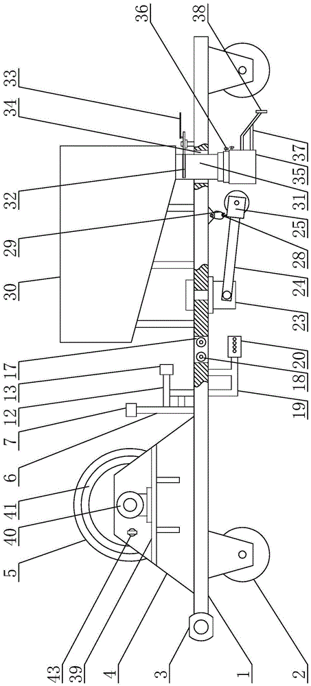
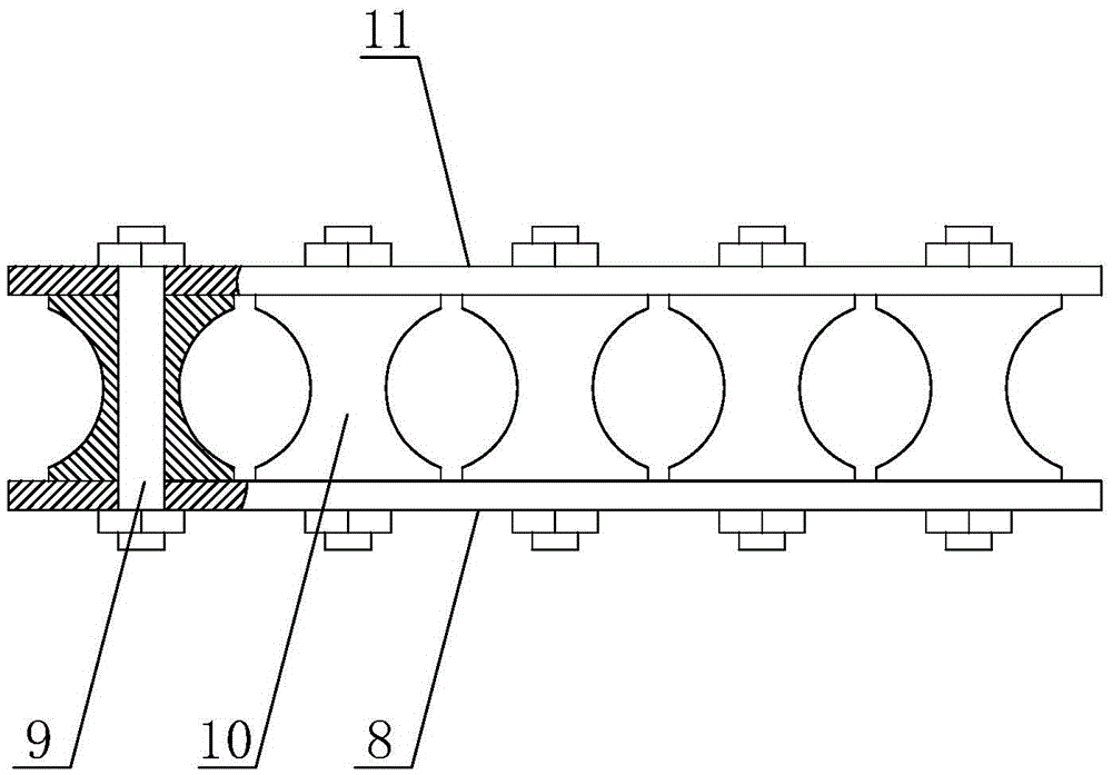
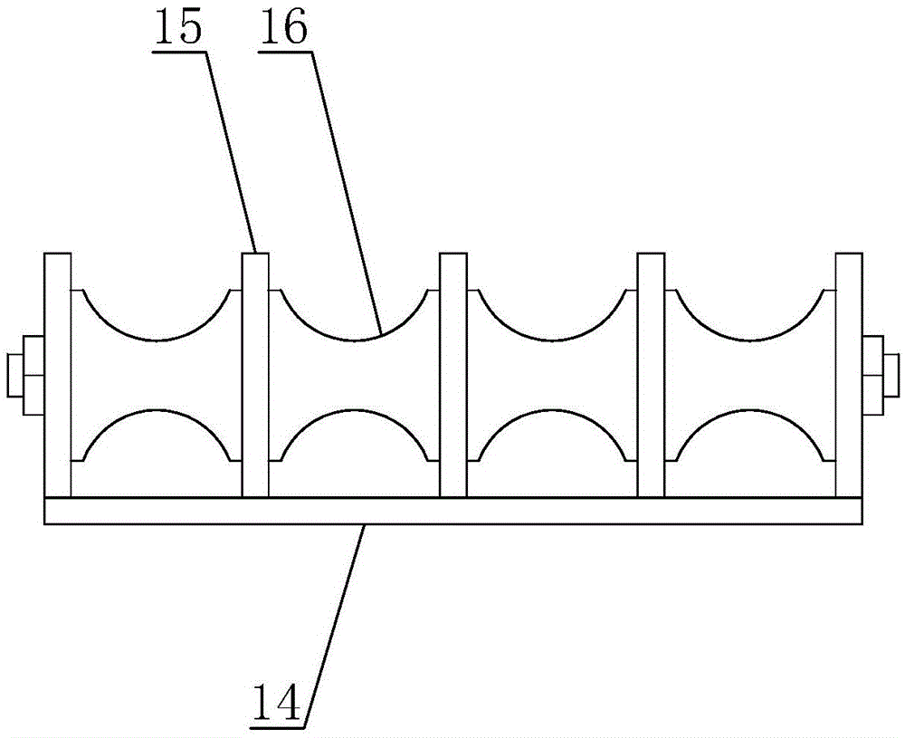
[0034] Embodiment: The present invention is a direct-buried cable laying device, including a vehicle frame, four anti-skid wheels are installed on the bottom of the vehicle frame, and the end of the vehicle frame is welded with a traction hook, which can facilitate the connection between the vehicle frame and Tractor connection. A pay-off rack is arranged on the vehicle frame, and the pay-off rack is welded on the vehicle frame, and four reels are installed on the pay-off rack. The reel locking pin is arranged on the pay-off rack, which can lock the reel during the transfer process of the vehicle frame, prevent the cables on the reel from falling off, and facilitate transportation. A third support plate is arranged on the pay-off frame, and a motor is arranged on the third support plate, and the motor is connected to the wire reel by transmission, and the motor can drive the wire reel to rotate, which can reduce the tension on the cable during the cable laying process, and can...


PUM


Abstract

The invention discloses a buried cable laying device, and mainly relates to the technical field of electric power construction. The buried cable laying device comprises a vehicle frame, the vehicle frame is provided with a pay-off rack, the pay-off rack is provided with a plurality of spools, the top of a first support frame is provided with a hub, a support arm is provided with a guide frame, the vehicle frame is provided with a plurality of threading holes, a second support frame is provided with a tensioning rack, the bottom of the vehicle frame is provided with a rotation hydraulic cylinder, the rotation hydraulic cylinder is provided with a rotating arm, the rotating arm is provided with a U-shaped frame, the U-shaped frame is provided with rolling wheels, the vehicle frame is provided with a box body, the bottom of the box body is provided with a cloth-sand pipe, the bottom of the cloth-sand pipe is provided with a telescoping pipe, the lower part of the telescoping pipe is provided with a scraper frame, and the scraper frame is provided with a smoothing scraper. The beneficial effects of the buried cable laying device are that laying and sand filling of the buried cable can be accomplished, a lot of manpower resources can be saved, the workload of construction personnel can be reduced, and the construction efficiency can be improved.

Description

technical field [0001] The invention relates to the technical field of electric power construction, in particular to a direct buried cable laying device. Background technique [0002] The direct buried cable is in accordance with the requirements of the specification. After the direct buried cable trench is dug, a sand cushion is laid on the bottom of the trench, and the sundries in the trench are removed, and then the cable is laid. A cable laying method in which a brick or concrete slab is covered on the cable to protect the cable and then backfilled. [0003] At present, in the laying process of direct-buried cables, the cables are often laid along the direction of the direct-buried cable trenches by human traction or tractor traction, and then sand is filled into the direct-buried cable trenches. Occupy a large amount of human resources, the workload of the construction personnel is heavy, and the construction efficiency is low. Contents of the invention [0004] The...

Claims


Application Information

Patent Timeline
IPC IPC(8): H02G1/08
CPCH02G1/088
Inventor 武庆民刘可姜谭赵彬孙健孙善朋
Owner JIYANG POWER SUPPLY CO STATE GRID SHANDONG ELECTRIC POWER CO
Learn More