
Depth sensor system

A technology of depth sensing and sensing unit, applied in the field of image processing, which can solve the problems of slow depth information extraction process, limited lighting conditions of a single light-emitting unit, possibility of surface texture and color occlusion, difficulty in updating, etc.

Active Publication Date: 2016-04-13
LENOVO (BEIJING) CO LTD
View PDF4 Cites 9 Cited by
  • Summary
  • Abstract
  • Description
  • Claims
  • Application Information

AI Technical Summary

Problems solved by technology

However, since a single light-emitting unit is limited by issues such as lighting conditions, surface texture and color, and occlusion possibilities, the accuracy of target object extraction is not enough, and it is difficult to obtain accurate depth information for precise target objects
If the target object is not extracted and only the matching algorithm of the two image sensors is used, the depth information extraction process is very slow due to the large amount of calculation, and it is difficult to update in real time

Method used


Image

  • Depth sensor system
  • Depth sensor system
  • Depth sensor system

Examples


Embodiment Construction

[0016] Various embodiments according to the present invention will be described in detail with reference to the accompanying drawings. Here, it is to be noted that, in the drawings, the same reference numerals are assigned to components having substantially the same or similar structures and functions, and repeated descriptions about them will be omitted.

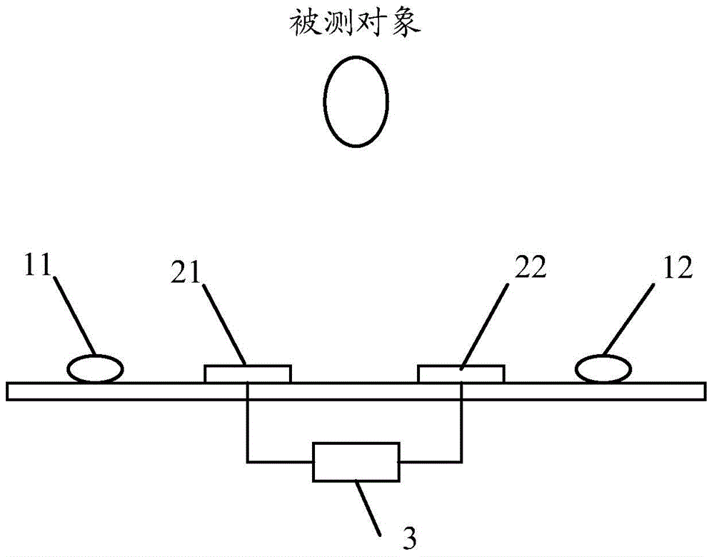
[0017] figure 1 is a schematic diagram illustrating a depth sensing system according to one embodiment of the present invention. Here, the depth sensing system according to the embodiments of the present invention can be applied to electronic devices such as smart phones, tablet computers, notebook computers, and smart TVs.

[0018] Such as figure 1 As shown, the depth sensing system according to the embodiment of the present invention may include a first light emitting unit 11 , a second light emitting unit 12 , a first sensing unit 21 , a second sensing unit 22 and a processing unit 3 .

[0019] For example, the first ...


PUM


Abstract

The invention relates to a depth sensor system. The system comprises a first luminescent unit used as a first light source; a second luminescent unit used as a second light source; a first sensor unit used for sensing light reflected by a detected object so as to collect at least one first image data; a second sensor unit used for sensing light reflected by the detected object so as to collect at least one second image data; and a processing unit used for exporting depth information of the detected object according to the at least one first image data and the at least one second image data, wherein the first luminescent unit and the second luminescent unit are configured in different positions relative to the first sensor unit and the second sensor unit, and the first luminescent unit and the second luminescent unit irradiate the detected object at a preset time.

Description

technical field [0001] The present invention relates to the field of image processing, and more particularly, the present invention relates to a depth sensing system. Background technique [0002] A real-time depth camera is capable of determining the distance to a human or other object within the camera's field of view and updating that distance in substantially real-time based on the camera's frame rate. Such a depth camera may be used, for example, in a motion capture system to acquire data about the position and movement of a human body or other subject in physical space, and this data may be used as input to an application in a computing system. Various applications already exist, such as for military, entertainment, sports and medical purposes. [0003] Typically, depth sensing systems in currently known depth cameras employ a single light emitting unit for illuminating the field of view, and two image sensors for sensing light from the field of view to form an image....

Claims


Application Information

Patent Timeline
IPC IPC(8): H04N5/335H04N13/02
Inventor 阳光
Owner LENOVO (BEIJING) CO LTD
Learn More