
A rail anchor point and a backing plate for that rail anchor point

一种固定点、轨道的技术,应用在固定轨条、轨道、道路等方向,能够解决制造技术方面昂贵等问题,达到优化可简易安装、尺寸小、重量轻的效果

Active Publication Date: 2018-05-11
VOSSLOH WERKE GMBH
View PDF8 Cites 0 Cited by
  • Summary
  • Abstract
  • Description
  • Claims
  • Application Information

AI Technical Summary

Problems solved by technology

However, this arrangement is rather expensive in terms of production technology, since different inclinations of the rail have to be realized for curves of different curvature

Method used


Image

  • A rail anchor point and a backing plate for that rail anchor point
  • A rail anchor point and a backing plate for that rail anchor point
  • A rail anchor point and a backing plate for that rail anchor point

Examples


Embodiment Construction

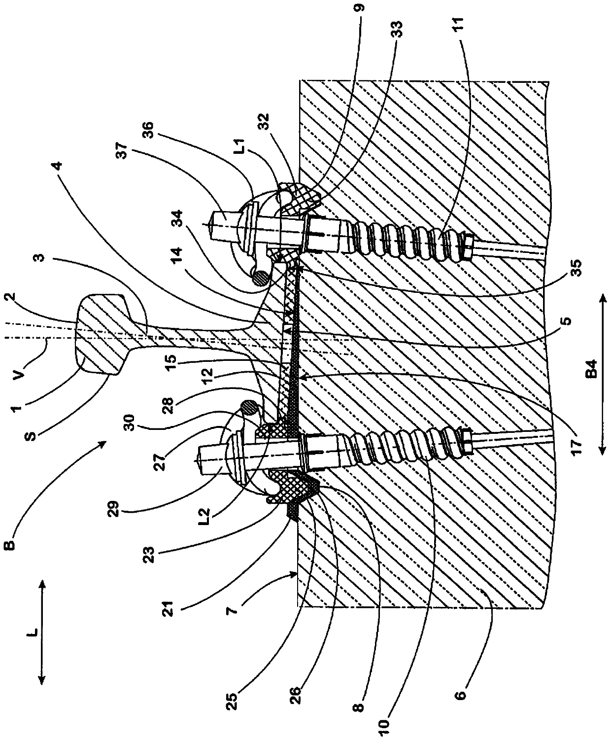
[0041] Track S is fixed on the attached figure 1 At the track fixing point B shown in, it usually has: a rail head 1, on the upper side of which is formed a running surface 2 for a rail wheel (also not shown) of a rail vehicle (not shown); The rail web 3 supporting the rail head 1; and the rail bottom 4, which is arranged in the center of the rail bottom. The rail bottom 4 is wider than the rail head 1 and has a flat supporting surface 5 on its underside.

[0042] The track fixing point B includes a foundation 6, which in this embodiment is formed by a common type of sleeper cast by concrete. The foundation 6 has a flat contact surface 7 on its upper side, which extends with the length of the foundation 6 measured transversely to the longitudinal direction L of the foundation aligned with the track S.

[0043] Two groove-shaped grooves 8 and 9 are formed on the contact surface 7 at intervals, and the two grooves extend parallel to each other and parallel to the longitudinal extens...


PUM


Abstract

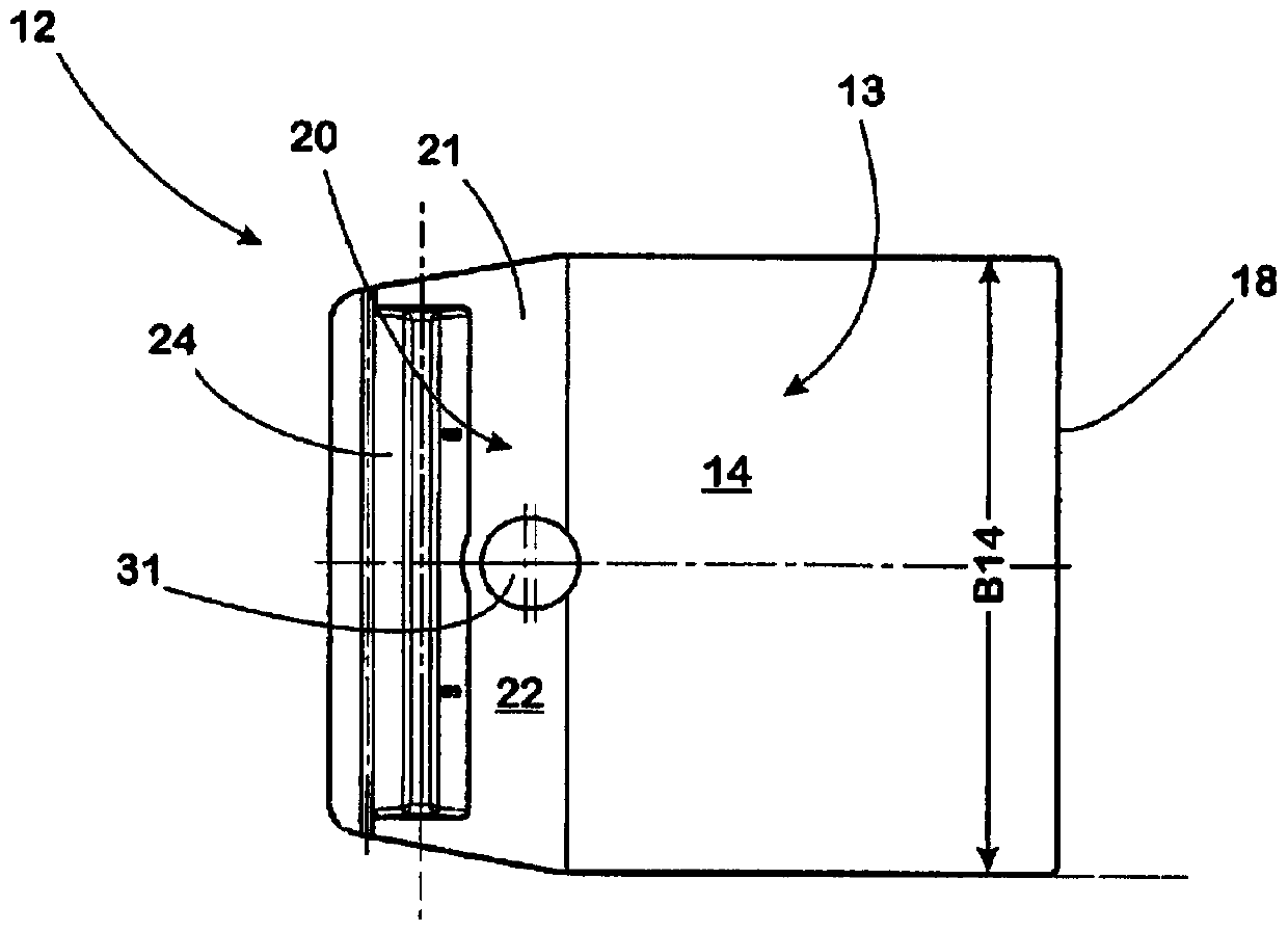
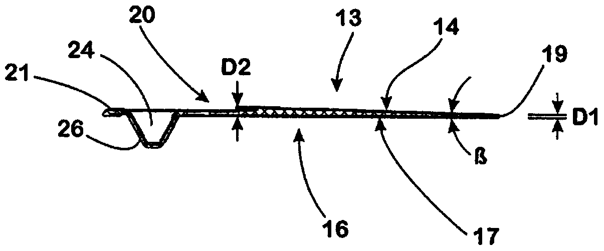
The invention relates to a rail fixing point for a rail (S) of a rail vehicle on a foundation (6) and a backing plate for the rail fixing point, said rail fixing point comprising two guide plates (23, 32) and a backing plate (12) arranged between the foundation (6) and the track (S), wherein each guide plate (23, 32) corresponds to a longitudinal side (L1, L2) of a track (S), wherein the backing plate (12) has a contact surface (14) on its upper side (13), on which the rail (S) is supported in the installed state, the backing plate has a support surface on its underside, the backing plate in the installed state (12) is supported on the foundation (6) by the support surface, and wherein the contact surface and the support surface of the backing plate (12) form an acute angle (β ).

Description

Technical field [0001] The invention relates to a track fixing point on which a track for a rail vehicle is fixed to a foundation. The rail to be fixed in this type of fixing point usually has: a rail head for the running surface of the rail wheel of a rail vehicle, a rail web supporting the rail head, and a rail bottom are formed on its upper side, viewed in cross section , The rail bottom is obviously wider than the rail head and the rail web, and the rail web stands on the rail bottom. At the position where the installation is completed, the rail is erected on each foundation at the bottom of the rail, and various layers can be provided between the rail and the foundation to facilitate contact between the rail and the foundation. Background technique [0002] In this way, a plate-shaped intermediate layer can be arranged between the bottom of the rail and the foundation, and the intermediate layer is made of a material with accurately defined elasticity, and can ensure that t...

Claims


Application Information

Patent Timeline
Patent Type & Authority Patents(China)
IPC IPC(8): E01B9/68
CPCE01B9/685E01B9/68E01B9/40
Inventor 安德烈·胡诺尔德温弗里德·博斯特林
Owner VOSSLOH WERKE GMBH
Learn More