Rotary air lock feeding valve

A feeding valve and rotary feeding technology, applied in grain processing and other directions, can solve the problems of increasing the wear of the drive shaft, increasing the load of the whole machine, abnormal noise of the drive shaft, etc., so as to achieve reliable operation, high rigidity and strength, and use long life effect

Inactive Publication Date: 2016-04-20
GUANGXI BRILLIANT MACHINERY CO LTD
View PDF8 Cites 3 Cited by
  • Summary
  • Abstract
  • Description
  • Claims
  • Application Information

AI Technical Summary

Problems solved by technology

The existing rotary air lock feeding valve has the following defects: 1. In the process of conveying materials, if the materials are wet, they are easily bonded to the inner wall of the leveling tank, which not only increases the load of the whole machine, but also reduces the material conveying efficiency. Shut down to clean up the sticky material, which affects the normal use of the rotary air lock feeding valve; 2. When the rotary body rotates, the fine materials in the leveling tank are easy to enter between the outer edge of the end wall at both ends of the leveling tank and the inner wall of the feeding valve body Small materials fall into the gap between the inner wall of the feed valve body and the end walls at both ends of the trough. The accumulation of fine m

Method used


Image

  • Rotary air lock feeding valve
  • Rotary air lock feeding valve
  • Rotary air lock feeding valve

Examples


Embodiment Construction

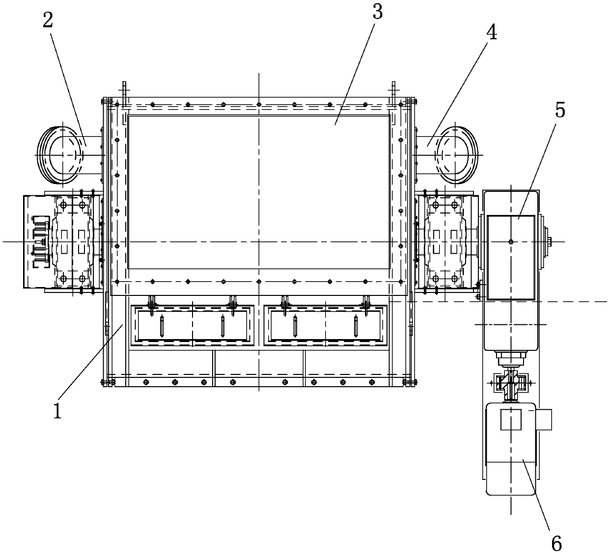
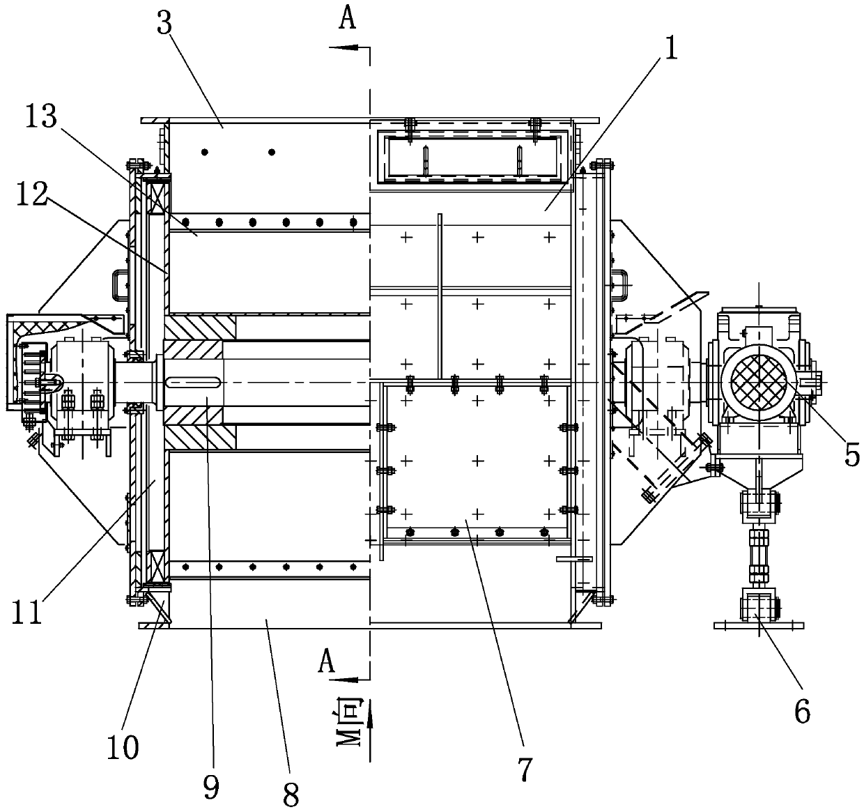
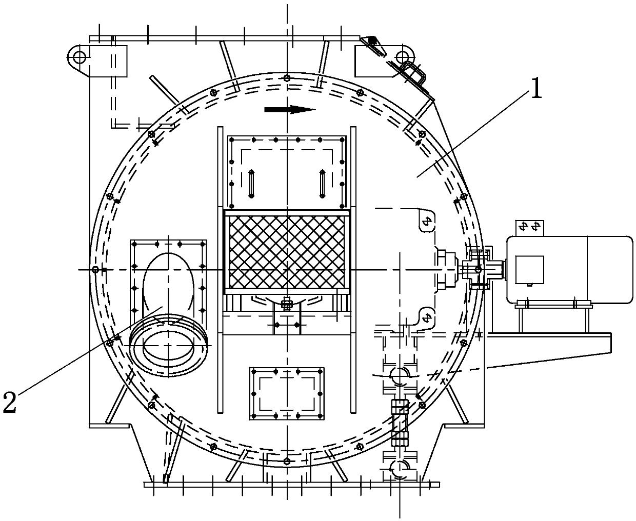
[0024] Such as Figure 1 to Figure 7 As shown, the rotary air lock feeding valve of the present invention includes a feeding valve body 1 , a driving device and a rotary feeding device arranged in the feeding valve body 1 . The feed valve body 1 is a box body welded by low-alloy high-strength steel plates. The upper end of the feed valve body 1 is provided with a feed port 3, the lower end of the feed valve body 1 is provided with a discharge port 8, and a cylindrical conveying space 18 is provided between the feed port 3 and the discharge port 8. The inner wall of the conveying space 18 is connected with a layer of inner liner 16 made of composite wear-resistant material.

[0025] The rotary feeding device includes a transmission shaft 9 and a revolving body connected outside the rotating shaft. The revolving body includes a plurality of throwing troughs 13 connected outside the drive shaft 9 in an annular array, and the ends of the groove walls 15 of adjacent throwing troug...


PUM


Abstract

The invention discloses a rotary air lock feeding valve, and relates to a material milling device. The material milling device comprises a feeding valve body, a driving device and a rotary feeding device, wherein the rotary feeding device comprises a drive shaft and a rotary body connected to the outer side of the rotary shaft; the rotary body comprises a plurality of material throwing grooves connected to the outer side of the drive shaft in an annular array mode; the tail ends of groove walls of adjacent material throwing grooves are connected with seal adjusting devices; the rotary feeding device is integrally installed in the feeding valve body, and two ends of the drive shaft are supported to the lateral wall of the feeding valve body and extend to outside of the side wall; openings of the material throwing grooves are toward the direction deviating from the radial direction of the drive shaft; the opening of each material throwing groove deviates from the radial direction of the drive shaft toward the same side; hot air channels are formed between inner walls of the adjacent material throwing grooves; two ends of the feeding valve body are respectively connected with an air intake channel and an air exhaust channel which are communicated with the hot air channels; the bottom ends of rotary clearances at two ends of the material throwing grooves are respectively provided with dual-row material openings communicated with a material outlet. The rotary air lock feeding valve has the advantages of operation reliability, long service life, maintenance convenience, no material sticking and the like.

Description

technical field [0001] The invention relates to material grinding equipment, in particular to an air-locking rotary feeding device of the grinding equipment. Background technique [0002] Material grinding equipment is widely used in power generation, mining, building materials, chemical industry and other industries. The rotary air lock feeding valve in material grinding equipment is mainly used to control the flow of relatively strong materials, block air circulation and evenly transport materials to the next receiving device. The rotary airlock feeding valve usually includes a feeding valve body, a driving device and a rotary feeding device installed in the feeding valve body. The rotating feeding device includes a transmission shaft and a rotating body connected outside the shaft. The transmission shaft can drive the rotation The rotating body rotates together, and the rotating body includes a plurality of leveling grooves connected to the outside of the transmission sh...

Claims


Application Information

Patent Timeline
IPC IPC(8): B02C23/02
CPCB02C23/02
Inventor 王建河梁建武宋刚强
Owner GUANGXI BRILLIANT MACHINERY CO LTD
Why Eureka
Try Eureka