Compound coating machine achieving quantitative coating liquid supply
A compound machine and coating technology, which is applied to the device and coating of the surface coating liquid, can solve the problems of not reaching the overall uniformity, not reaching the user, and dust sticking to it, so as to reduce pollution, Effect of protecting people's safety
- Summary
- Abstract
- Description
- Claims
- Application Information
AI Technical Summary
Problems solved by technology
Method used
Image

Examples
Embodiment Construction
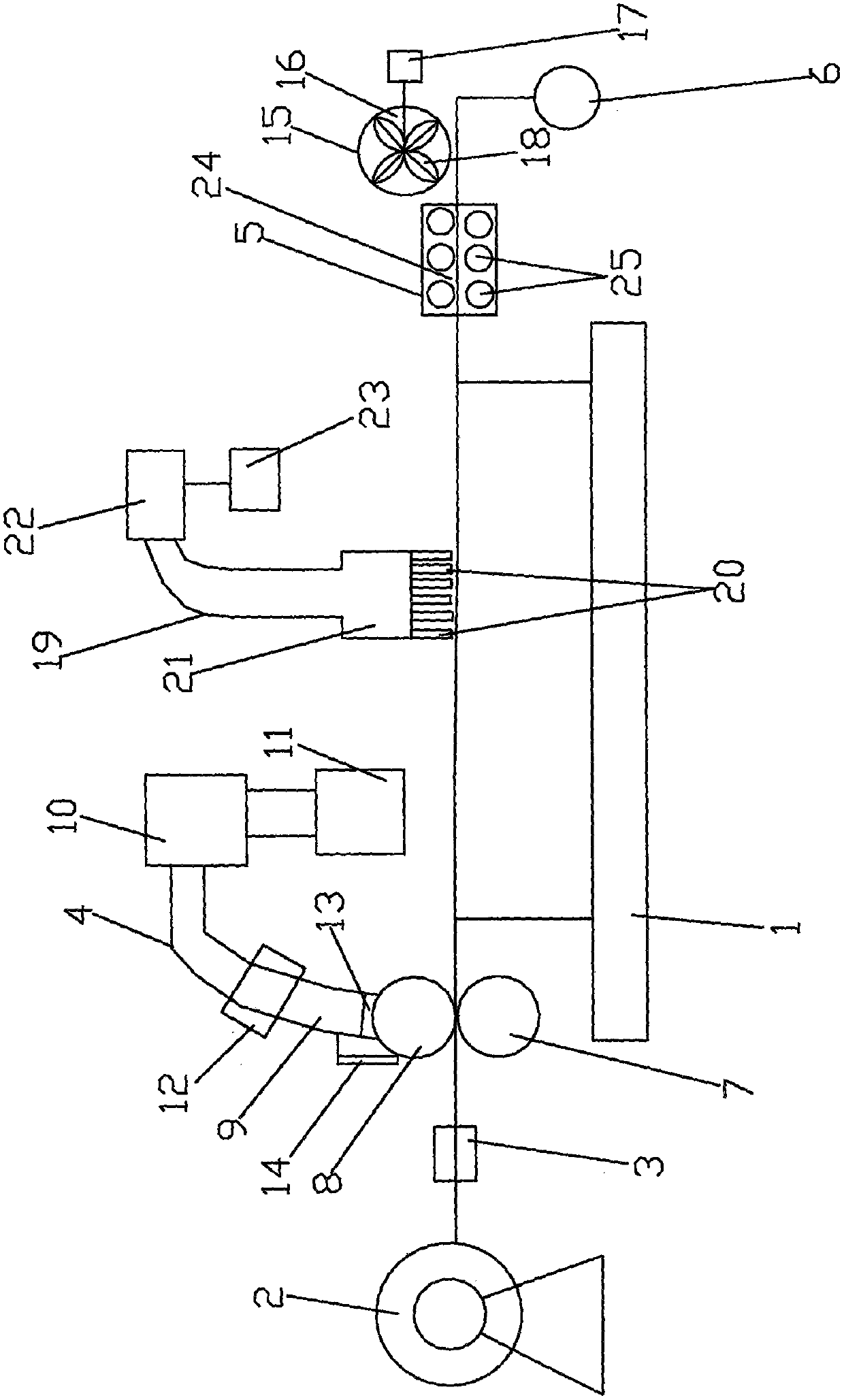
[0011] see figure 1 , a coating composite machine for quantitatively providing coating liquid, comprising a frame 1, an unwinding drum 2 is provided at the left end of the frame 1, and an output end of the unwinding drum 2 is connected to an edge correction mechanism 3, and the edge correction mechanism 3 The output end of the gluing device 4 is connected to the gluing device 4, the output end of the gluing device 4 is connected to the baking mechanism 5, the output end of the baking mechanism 5 is connected to the reel 6, the gluing device 4 includes a transmission roller 7, and the top of the transmission roller 7 A coating stick 8 is provided, and a drip tube 9 is arranged above the coating stick 8, and the drip tube 9 is connected to the liquid tank 11 through a pump 10, and a flow-limiting switch is set between the pump 10 and the drip tube 9 12. There is a scraper 14 at the mouth 13 of the dripping tube, and there is a gap between the scraper 14 and the coating roller 8 ...
PUM
 Abstract
Description
Claims
Application Information
PatSnap Eureka turns technology decisions into work you can execute. Powered by our Innovation Knowledge Graph, it runs expert workflows across engineering, life sciences, materials and intellectual property. Get your review-ready output in minutes.


