Optical fiber secondary coating device

A secondary plastic sleeve, optical fiber technology, applied in optics, light guides, optical components, etc., can solve the problem of inability to meet the production requirements of high-speed production of hydrogel-filled loose tubes or fully dry environmental protection optical cable loose tubes, unable to loosen The shrinkage rate of the casing is controlled within a reasonable range, which affects the production quality and production efficiency of the loose casing, so as to improve the production quality and production speed, improve the reliability, and ensure the stability.

Active Publication Date: 2016-04-20
YANGTZE OPTICAL FIBRE & CABLE CO LTD
View PDF4 Cites 16 Cited by
  • Summary
  • Abstract
  • Description
  • Claims
  • Application Information

AI Technical Summary

Problems solved by technology

[0002] The secondary coating process of optical fiber is to select suitable polymer materials, adopt extrusion process, and under reasonable process conditions, put a loose tube with the same length as the optical fiber on the optical fiber. Due to the shrinkage of the loose tube, the formed The loose tube only allows the tube to shrink in a small range. The traditional process can only control a small degree of shrinkage at a lower speed and limited materials to meet the requirements, but at a higher production speed and greater flexibility Material, especially when producing grease-free full-dry environmental protection casing at high speed, due to the large shrinkage of the dry loose casing at this time, the traditional production method cannot control the shrinkage of the loose casing within a reasonable range, which affects the loose casing. Casing production quality and productivity
And existing all kinds such as wheel type, belt-type casing press traction water tank device are fixed in the production process position, when the traction speed of production line changes, because the length of water tank device is fixed, make various The cooling time of the material loose tube in the water tank is inconsistent, resulting in inconsistent crystallinity, which cannot meet the production requirements of high-speed production of hydrogel-filled loose tube or fully dry environmental protection optical cable loose tube

Method used


Image

  • Optical fiber secondary coating device
  • Optical fiber secondary coating device
  • Optical fiber secondary coating device

Examples


Embodiment Construction

[0027] The present invention will be further described below in conjunction with accompanying drawing.

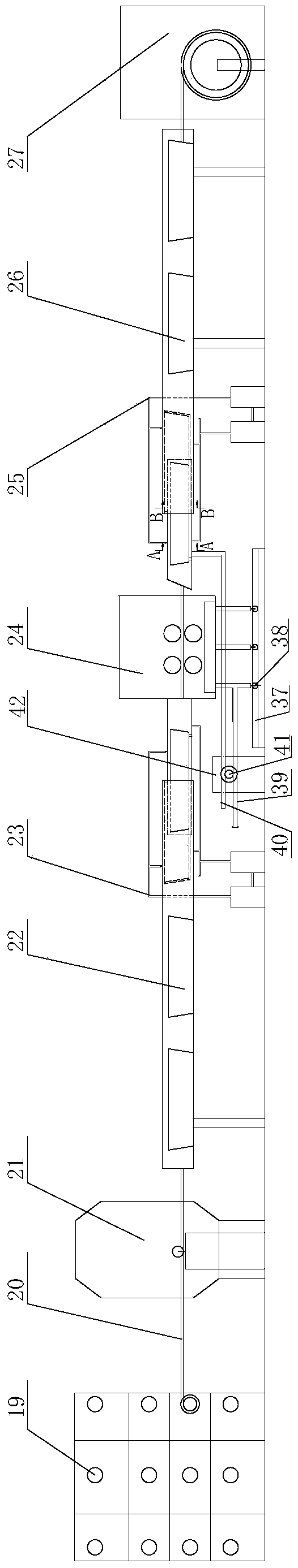
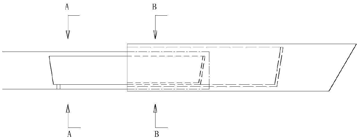
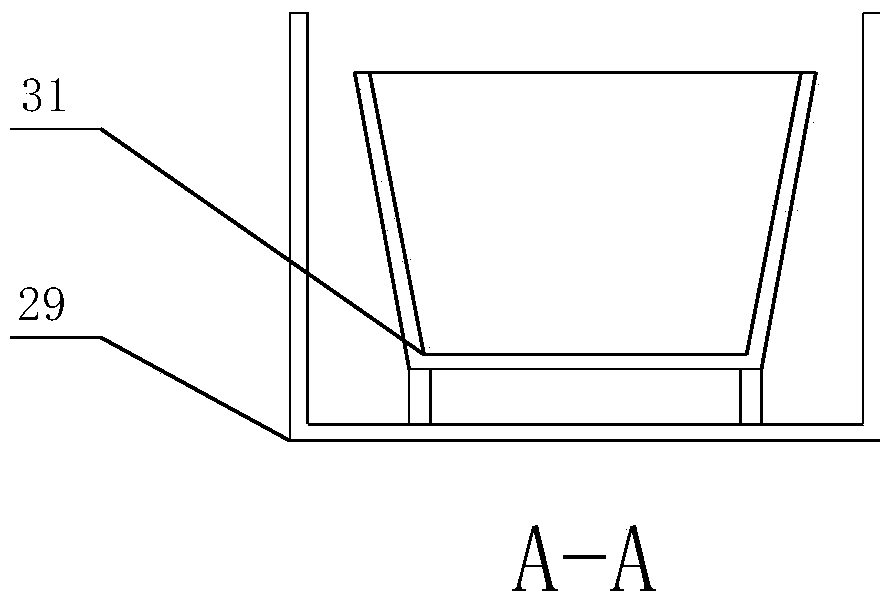
[0028] As shown in Figures 1-7, this embodiment provides a secondary plastic sheathing equipment for optical fibers, including an extruder head 19, a front cooling water tank device 22, a front cooling water supply device 23, and an optical cable loose tube shrinkage compensation device 24 , the rear cooling water tank device 26, the rear cooling water supply device 25, the optical fiber take-up device 27, the front cooling water tank device 22 and the rear cooling water tank device 26 are shrinkable water tank devices, and the front cooling water tank device 22 It shrinks or stretches synchronously with the cooling water tank device 26 at the rear stage.

[0029] In the present invention, the structure of the front cooling water tank device 22 and the rear cooling water tank device 26 is the same, therefore, there are many ways to realize the synchronous contraction or syn...


PUM


Abstract

The invention discloses an optical fiber secondary coating device. The optical fiber secondary coating device comprises an extrusion head, a front-section cooling water bath device, a front-section cooling water supplying device, an optical cable loose tube shrinkage compensation device, a rear-section cooling water bath device, a rear-section cooling water supplying device and an optical fiber take-up device, wherein both the front-section cooling water bath device and the rear-section cooling water bath device are contraction type water bath devices and contract or stretch synchronously. By controlling the cooling water bath devices at two ends to contract or stretch synchronously according to pulling speed, the cooling time of a loose tube is made consistent in the water baths, so that the degree of crystallinity is made consistent, and then the loose tube production requirement is met. Besides, the loose tube is further drawn through the optical cable loose tube shrinkage compensation device before complete crystallization to counteract the shrinkage percentage of the loose tube to a certain extent, so that the stability of the excess length of optical fiber in the loose tube is guaranteed and the production quality and production speed of optical fiber are improved.

Description

technical field [0001] The invention relates to the field of optical fiber communication, in particular to an optical fiber secondary plastic sleeve device. Background technique [0002] The secondary coating process of optical fiber is to select suitable polymer materials, adopt extrusion process, and under reasonable process conditions, put a loose tube with the same length as the optical fiber on the optical fiber. Due to the shrinkage of the loose tube, the formed The loose tube only allows the tube to shrink in a small range. The traditional process can only control a small degree of shrinkage at a lower speed and limited materials to meet the requirements, but at a higher production speed and greater flexibility Material, especially when producing grease-free full-dry environmental protection casing at high speed, due to the large shrinkage of the dry loose casing at this time, the traditional production method cannot control the shrinkage of the loose casing within a ...

Claims


Application Information

Patent Timeline
Patent Type & Authority Applications(China)
IPC IPC(8): B29C47/88B29C47/08B29C47/02G02B6/44B29C48/06
CPCB29C48/267B29C48/15B29C48/911G02B6/4479B29C48/06B29C48/919
Inventor 钟升黄杰熊壮
Owner YANGTZE OPTICAL FIBRE & CABLE CO LTD
Why Eureka
Try Eureka