Railway running device for road and rail dual-purpose vehicles

A technology for road-rail dual-purpose vehicles and running devices, which is applied to track and road dual-purpose vehicles, motor vehicles, transportation and packaging, etc. It can solve problems such as insufficient down pressure of guide wheels, large safety hazards of vehicles, and easy derailment, etc., to achieve The effect of improving positioning accuracy, avoiding potential safety hazards, and preventing derailment problems

Active Publication Date: 2017-10-10
CHANGZHOU RUITAI ENG MASCH CO LTD +1
View PDF8 Cites 0 Cited by
  • Summary
  • Abstract
  • Description
  • Claims
  • Application Information

AI Technical Summary

Problems solved by technology

The assembled guiding device has three problems due to the relatively fixed integrity of the connection. On the one hand, due to the relatively fixed connection between the guiding device and the vehicle, the vehicle must choose a wider level crossing when getting on and off the railway. Only when the iron car and the railway are adjusted to the same direction can the vehicle fall into the track, and the requirements for getting on and off the railway are relatively high
On the second aspect, it is difficult to adapt to the self-adjustment of the angle when the vehicle turns, and often faces the problem of insufficient curve radius when turning, and it is easy to climb the track and derail; third, for the truck, this guide device lacks effective Adjustment, when the vehicle is empty, it is easy to have insufficient down pressure on the guide wheel and easy to derail
[0003] These problems have brought great inconvenience to construction operations, and have also left great potential safety hazards for vehicles.

Method used


Image

  • Railway running device for road and rail dual-purpose vehicles
  • Railway running device for road and rail dual-purpose vehicles
  • Railway running device for road and rail dual-purpose vehicles

Examples


Embodiment Construction

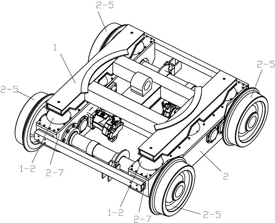
[0022] Such as figure 1 , 2 , 3, and 4, a railway running device for road-rail dual-purpose vehicle of the present invention includes an intermediate body 1 and a chassis 2, and the intermediate body 1 is mounted on the chassis 2 top,

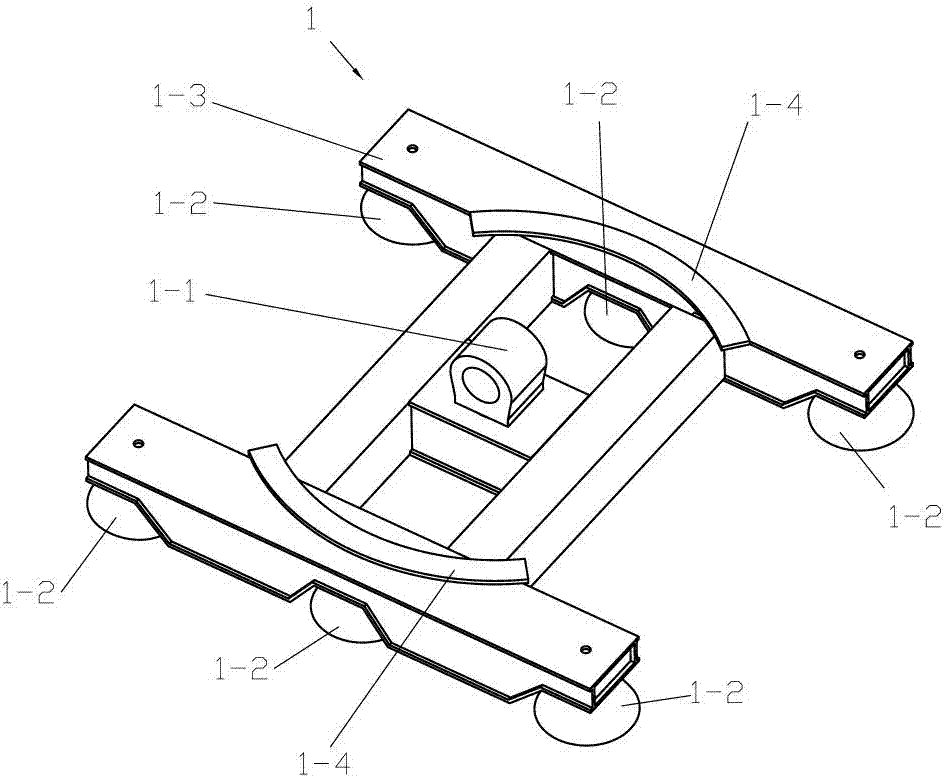
[0023] The intermediate body 1 includes a traction pin 1-1, a frame 1-3, a slide rail 1-4 and a shock absorber 1-2, the traction pin 1-1 is rotatably hinged on the frame 1-3, and the slide rail There are two of 1-4, and they are all fixed on the upper part of frame 1-3, and there are at least four damping blocks 1-2, and they are all fixed on the lower part of frame 1-3,

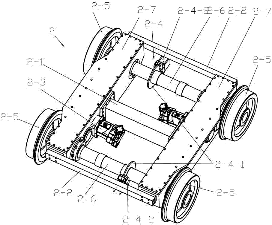
[0024] The chassis 2 includes a gearbox 2-7, an axle 2-6, a wheel 2-5, a support frame 2-1, an end connecting rod 2-2, a motor 2-3 and a braking device 2-4,

[0025] Described axle shaft 2-6 has 2, and the two ends of axle shaft 2-6 are all equipped with wheel 2-5,

[0026] There are 2 gear boxes 2-7, and they are all connected to 2 axles 2-6, and each gear box 2-7 is conn...


PUM


Abstract

The invention discloses a railway running gear of a road-railer in railway running vehicles. The railway running gear comprises a middle body and a chassis; the middle body is arranged on the upper portion of the chassis and comprises a traction pin, a framework, two sliding rails and four or more vibration reduction blocks, the traction pin is rotatably hinged to the framework, the two sliding rails are fixed to the upper portion of the framework, and the four or more vibration reduction blocks are fixed to the lower portion of the framework; the chassis comprises gear boxes, axles, wheels, a supporting frame, end connection rods, a motor and a brake device; the motor is in transmission connection with the gear boxes, the supporting frame is fixed between the middles of the two gear boxes, and the end connection rods are fixed between the ends of the two gear boxes respectively; the brake device comprises brake discs and brake clamps, the brake discs are arranged on the axles, the brake clamps are arranged on the end connection rods or the gear boxes or the supporting frame, and the brake clamps are matched with the brake discs. The railway running gear has high rotational freedom, the railway running gear can get on and get off a rail conveniently and fast, and derail of a climbing rail can be prevented in the turning process.

Description

technical field [0001] The invention relates to a railway running vehicle, in particular to a railway running device for a road-rail vehicle. Background technique [0002] At present, road-rail vehicles are widely used in the rail transportation industry because they can run on both roads and railways. Road-rail vehicles are usually used for railway traction, emergency repair, construction and emergency operations. From a structural point of view, most road-rail dual-purpose vehicles today adopt the method of installing a railway guide device on the road vehicle. Driving on the railway relies on the rubber tires of the car to provide friction, and the railway wheels provide guidance. The assembled guiding device has three problems due to the relatively fixed integrity of the connection. On the one hand, due to the relatively fixed connection between the guiding device and the vehicle, the vehicle must choose a wider level crossing when getting on and off the railway. Only ...

Claims


Application Information

Patent Timeline
Patent Type & Authority Patents(China)
IPC IPC(8): B60F1/00
CPCB60F1/00
Inventor 耿路峰王印军陈建陈亚东
Owner CHANGZHOU RUITAI ENG MASCH CO LTD
Why Eureka
Try Eureka