A material pneumatic conveying system driven by a multi-piston sheath

A pneumatic conveying and multi-piston technology, applied in conveyors, conveying bulk materials, transportation and packaging, etc., can solve the problems of high matching degree between sample bottles and pipelines, precipitation, high cost of use, etc., and achieve various pneumatic conveying methods, The production process is simple and the maintenance cost is reduced

Active Publication Date: 2018-07-03
HUNAN SUNDY SCI & TECH DEV
View PDF8 Cites 0 Cited by
  • Summary
  • Abstract
  • Description
  • Claims
  • Application Information

AI Technical Summary

Problems solved by technology

The staff needs to design the material to be transported according to the size of the pipeline, or design the pipeline according to the size of the sample bottle. There are problems such as difficult processing of pipes and sample bottles, high cost of use, and very inconvenient operation.
[0006] (2) The compatibility of this delivery method is also extremely poor
Due to the high matching requirements of the sample bottle and the pipeline, the operator cannot realize the delivery of various specifications of the sample bottle in the same delivery pipeline.
At the same time, this method has no protection for the sample bottle, and the high air pressure directly acts on the sample bottle to push the sample bottle forward, which may easily cause serious consequences such as sample bottle rupture or even sample bottle explosion.
[0007] (3) Vials are prone to stuck during transportation in this way
Because this method uses the sample bottle and the pipeline to match, when the sample bottle is deformed or damaged, it is easy to cause the sample bottle to be stuck during the transmission process, which affects the transmission efficiency and high maintenance costs
At the same time, due to the long-term contact and friction between the sample bottle and the pipeline, it is easy to cause wear and tear on the pipeline and damage to the sample bottle. It is necessary to replace the pipeline or sample bottle irregularly, and the use cost is high
[0008] (4) In this mode of transportation, the sample bottle directly rubs against the pipeline, and the frictional heat during high-speed transmission (10 meters per second) will cause the sample water in the sample bottle to be analyzed or oxidized, affecting the physical characteristics and accuracy of the sample

Method used


Image

  • A material pneumatic conveying system driven by a multi-piston sheath
  • A material pneumatic conveying system driven by a multi-piston sheath
  • A material pneumatic conveying system driven by a multi-piston sheath

Examples


specific Embodiment 1

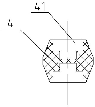
[0049] Specific embodiment 1: as Figure 4 As shown, the fixed part 41 includes a protective chamber 44 that is recessed on the piston sheath 4, and the two ends of the object to be conveyed 3 are respectively carried in the protective chambers 44 of the two front and rear piston sheaths 4 so that the object to be conveyed 3 does not come into contact with the protective chamber 44. When the transmission pipeline unit 1 contacts, the opening end of the protective chamber 44 is provided with a matching guide part 45. When the piston sheath 4 pushes the object 3 to be conveyed, the guide part 45 first contacts the object 3 to be conveyed and will push the object 3 to be conveyed under the action of the thrust. The object 3 is introduced into the protection chamber 44.

[0050] Through such setting, it has the following advantages: First, because the object to be conveyed 3 is carried on the protection chamber 44 and does not contact the transmission pipeline unit 1, the front an...

specific Embodiment 2

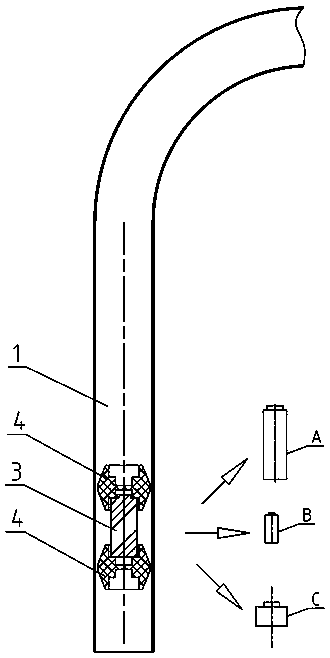
[0054] Specific embodiment 2: as image 3 with Figure 5 As shown, in this preferred embodiment, the axial ends of the piston sheath 4 are symmetrically tapered, so that the overall shape of the piston sheath 4 is a drum shape with thin ends and a thick middle, so that when the piston sheath 4 is stationary Contact with the transfer pipe unit 1 is maintained only through the axial middle. Through such a special scientific design, first, the contact surface between the piston sheath 4 and the transmission pipeline unit 1 is small, reducing the friction between the piston sheath 4 and the transmission pipeline, and the transmission resistance is small; second, this special structure makes the piston sheath 4 4. During the high-speed pneumatic conveying in the conveying pipe unit 1, it can flexibly adapt to the direction of the pipe, and effectively prevent the piston sheath 4 from turning over and being stuck.

specific Embodiment 3

[0055] Specific embodiment 3: as Image 6 As shown, in a preferred embodiment, the outer peripheral wall of the piston sheath 4 is provided with a plurality of ribs 42 arranged along the axial direction of the piston sheath 4 . In this embodiment, a plurality of raised ribs 42 are evenly arranged on the outer peripheral wall of the piston sheath 4, and the ribs 42 are in contact with the pipeline inner wall of the transmission pipeline unit 1, so that the piston sheath 4 is in contact with the transmission pipeline unit 1 The surface is small, reducing the friction between the piston sheath 4 and the transmission pipeline, and the transmission resistance is small.


PUM


Abstract

The invention discloses a material pneumatic conveying system driven by multiple piston sheaths, comprise a conveying line unit and a driving air source unit. A material to be conveyed is disposed inside the conveying line unit. The driving air source unit is communicated with the conveying line unit so as to produce positive / negative pressure in the conveying line unit, more than two piston sheaths fitting a conveying line are also disposed inside the conveying line unit, the material to be conveyed is disposed between adjacent two of the piston sheaths and lies in contact with the axial ends of both piston sheaths, and the piston sheaths move in the conveying line unit under the action of the driving air source unit so as to drive the material to be conveyed, for pneumatic conveying. This system has the advantages of good compatibility, low cost of use, conveying convenience and quickness, high safety and the ability to ensure physical features of a sample and precision.

Description

technical field [0001] The invention mainly relates to the field of equipment for collecting and processing material samples, in particular to a material pneumatic conveying system driven by a multi-piston sheath. Background technique [0002] For the sampling, sample preparation, and testing of material (such as ore, coal) samples, each country has mandatory standards, and the sampling and processing of samples must be carried out in accordance with the standards. The principle of sample sampling, sample preparation, and testing work process is to gradually reduce the particle size and quality of the collected samples without destroying the representativeness of the sample, until it meets the particle size and quality of the sample in the laboratory test ( Weight) accuracy requirements, and then carry out relevant laboratory analysis on the samples that meet the requirements. [0003] For example, taking coal sampling as an example, it is actually a sampling and analysis p...

Claims


Application Information

Patent Timeline
Patent Type & Authority Patents(China)
IPC IPC(8): B65G53/16
CPCB65G53/16B65G2812/1658
Inventor 朱先德朱青任率刘清海王芹
Owner HUNAN SUNDY SCI & TECH DEV
Why Eureka
Try Eureka