Transformer cooling fin spot welding machine

A heat sink and spot welding machine technology, applied in welding equipment, auxiliary welding equipment, welding/cutting auxiliary equipment, etc., can solve the problems of reduced performance, debris entry, unfavorable heat dissipation of components, etc., to accelerate heat dissipation , prolong the service life and improve the performance

Active Publication Date: 2022-06-28
江苏长川科技有限公司
View PDF5 Cites 1 Cited by
  • Summary
  • Abstract
  • Description
  • Claims
  • Application Information

AI Technical Summary

Problems solved by technology

[0004] In order to solve the above-mentioned technical problems, the present invention provides a spot welding machine for heat sinks of transformers, which solves the problems in the control mechanism of existing spot welding machines after working for a long time. Some components will generate high temperature, which will affect the pressure life of the equipment and make it unable to work normally. Some are heat dissipation mechanisms for heat dissipation, but for some areas with a lot of dust, hair and other sundries, a large amount of sundries will enter the mechanism Inside, debris deposits are formed, which is not conducive to the heat dissipation of components, and with the arrival of the rainy season, the air humidity is high, and debris adheres to the surface of components, which requires manual cleaning on a regular basis, which accelerates the aging of components and reduces the Problems with performance

Method used


Image

  • Transformer cooling fin spot welding machine
  • Transformer cooling fin spot welding machine
  • Transformer cooling fin spot welding machine

Examples


Embodiment 1

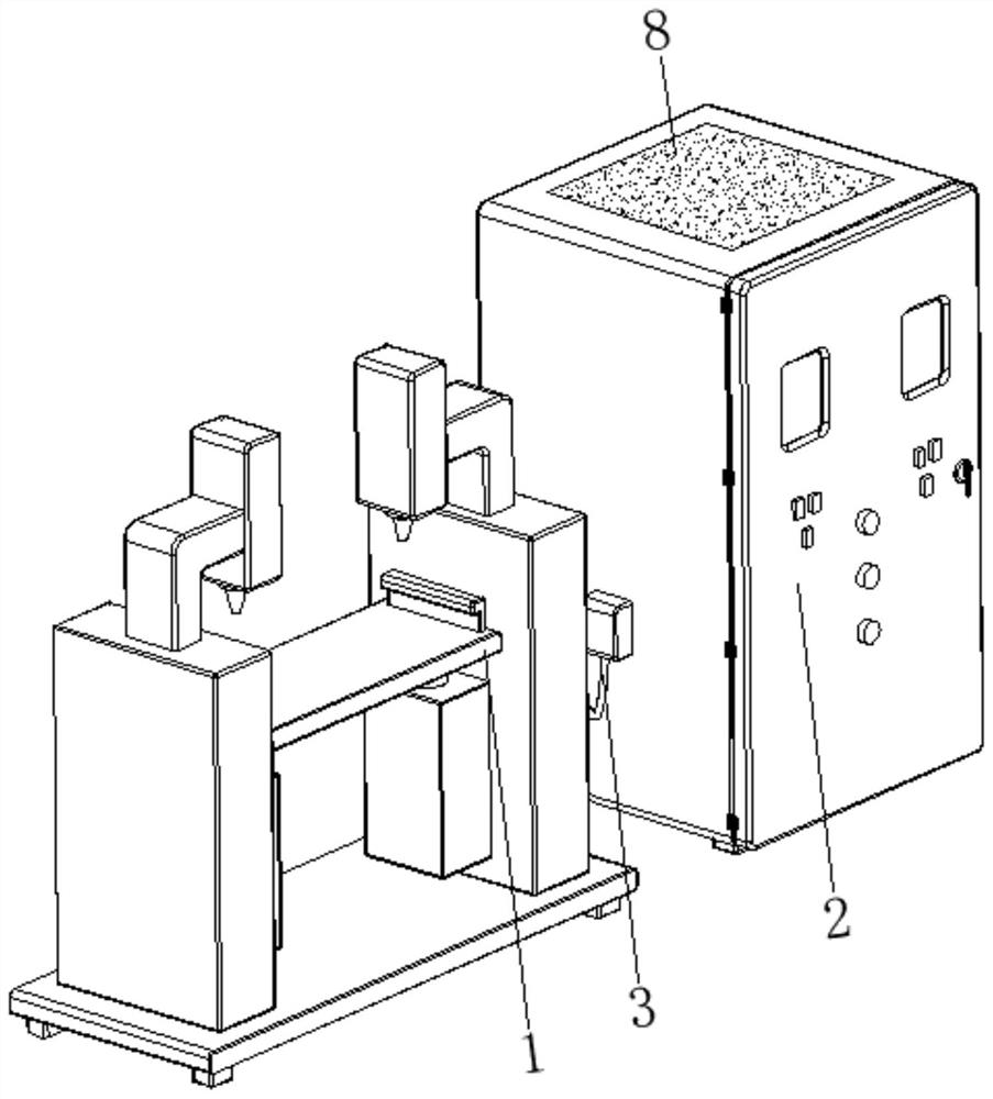
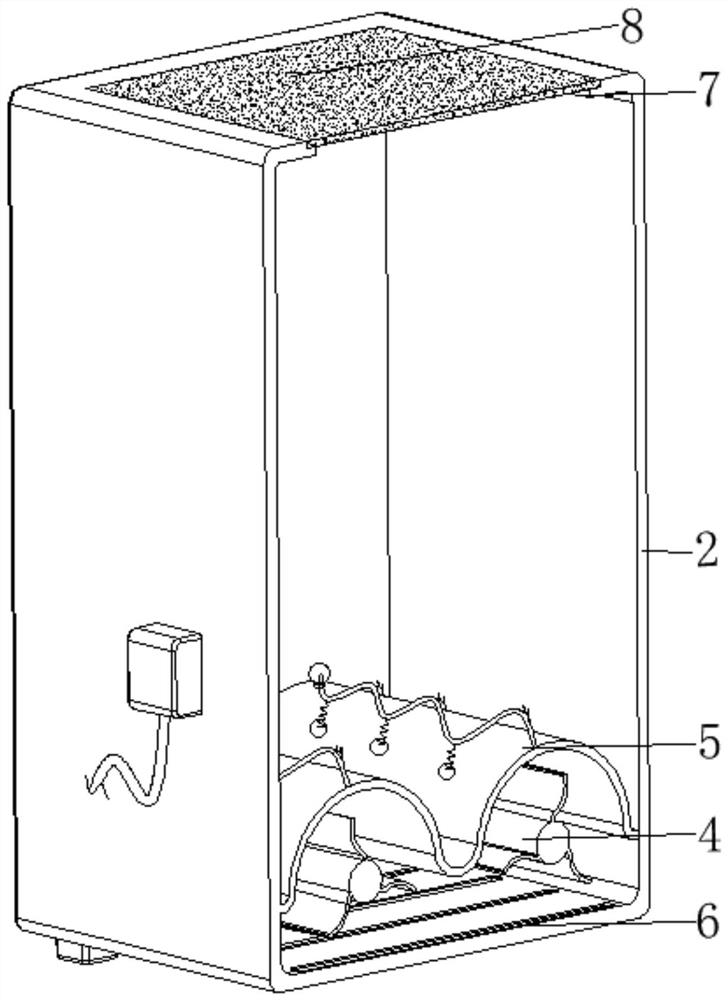
[0033] see Figure 1-Figure 8 , The present invention provides a technical solution: a transformer heat sink spot welding machine, comprising a body 1, a control cabinet 2, a connecting wire 3, a heat dissipation device 4, and an impurity removal device 5. The control cabinet 2 is arranged on one side of the body 1, The body 1 and the control cabinet 2 are connected by a connecting wire 3, the heat sink 4 is arranged at the bottom of the inner wall of the control cabinet 2, and the impurity removal device 5 is arranged inside the control cabinet 2 and close to the position of the heat sink 4;

[0034] The bottom of the control cabinet 2 is provided with a rectangular hole 6, the central position of the top of the control cabinet 2 is provided with an air outlet 7, and the top of the control cabinet 2 is fixedly connected with a dust-proof cotton 8 at the position of the air outlet 7. After the roller body 42 is driven by the power mechanism, the heat dissipation device 4 can d...

Embodiment 2

[0036] The heat sink 4 is provided with a base 41 , a roller body 42 , a blade 43 , a brush 44 , and a pressing device 45 . The bottom of the base 41 is fixedly connected to the bottom of the inner wall of the control cabinet 2 , and the end of the roller body 42 is connected to the base 41 . The top of the place is rotated and connected, the surface edge side of the blade 43 is fixedly connected with the surface of the roller body 42, the brush 44 is arranged on the surface edge of the blade 43 and is away from the side of the roller body 42, and the pressing device 45 is arranged on the roller body 42. At the end of the surface and close to the position of the blade 43, when the roller body 42 is driven by the power mechanism to rotate, the blade 43 and the top pressing device 45 also rotate at this time, thereby blowing the air inside the control cabinet 2 and making the control The air inside the cabinet 2 is discharged from the air outlet 7. At this time, the outside air e...

Embodiment 3

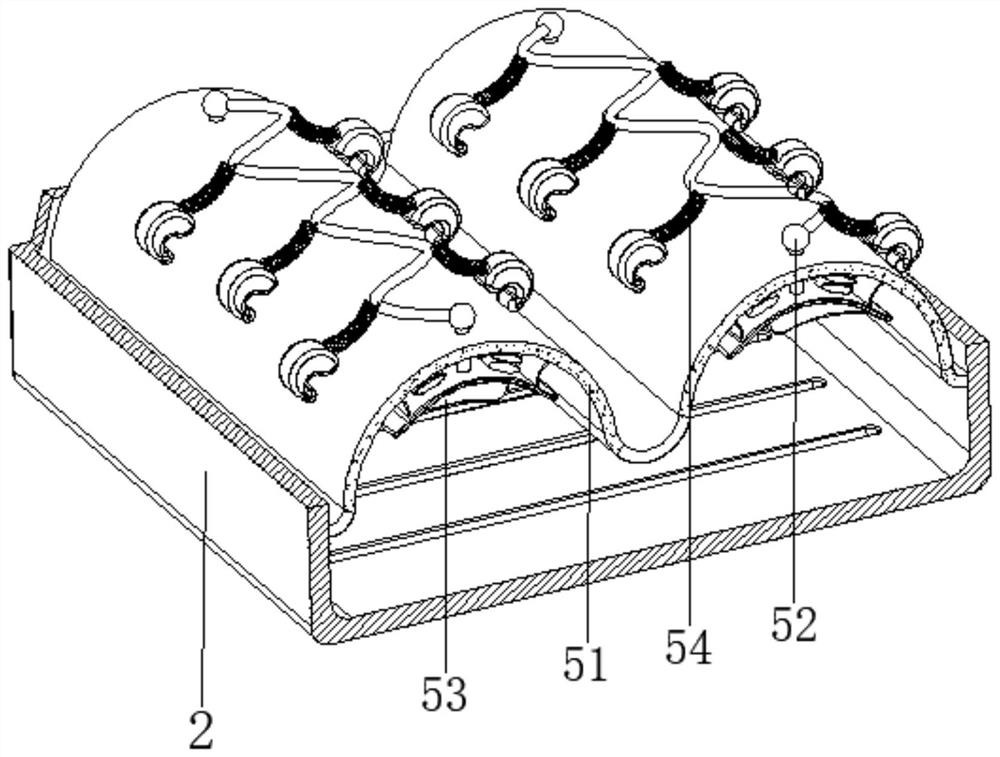
[0040] The pressure driving device 53 is provided with an arc-shaped elastic member 531, an arc-shaped base plate 532, a pressing block device 533, and a rubber elastic member 534. The top of the arc-shaped elastic member 531 is fixedly connected with the bottom of the butterfly filter screen 51. The arc-shaped base plate 532 The top of the base plate 532 is fixedly connected to the bottom end of the arc-shaped elastic member 531, and the top of the arc-shaped base plate 532 is fixedly connected to the bottom end of the ball head slider 52. The pressing block device 533 is arranged at the bottom center of the arc-shaped base plate 532, and the rubber elastic member 534 It is arranged between the two sides corresponding to the bottom of the butterfly filter 51 and the top of the arc-shaped base plate 532. When the rotating top pressing member 451 exerts top pressure on the pressing block body 5331 on the pressing block device 533, at this time, the ball Under the sliding and gui...


PUM


Abstract

The transformer cooling fin spot welding machine comprises a machine body, a control cabinet, a connecting wire, a cooling device and an impurity removing device, the cooling device is arranged at the bottom of the inner wall of the control cabinet, the impurity removing device is arranged in the control cabinet and is close to the cooling device, and the surface edge of a butterfly-shaped filter screen is fixedly connected with the inner wall of the control cabinet; the pressed driving device is arranged at the bottom of the butterfly-shaped filter screen and close to the ball head sliding rod, the cleaning device is arranged at the top end of the ball head sliding rod and close to the top of the butterfly-shaped filter screen, the top end of the supporting spring is fixedly connected with the surface of the connecting piece, and the surface end of the knocking head is fixedly connected with the bottom end of the supporting spring. The invention relates to the technical field of spot welding equipment. According to the transformer cooling fin spot welding machine, the self-cleaning effect is achieved, components can be cooled in time, sundries can be treated in time, self-cleaning is conducted, sundries are not prone to deposition, the service life of equipment is prolonged, safety and reliability are achieved, and the use performance is improved.

Description

technical field [0001] The invention relates to the technical field of spot welding equipment, in particular to a transformer heat sink spot welding machine. Background technique [0002] Power transformers are an indispensable key equipment in the process of power transmission. With the continuous acceleration of the country's modernization process and the continuous improvement of people's living standards, with the upgrading of power transformers, the use of power transformers is increasing. The transformer heat sink is an important part of the transformer equipment. Its main function is to dissipate the heat of the transformer during operation to ensure the normal operation of the transformer. During the processing of the transformer heat sink, in order to ensure the bonding effect between the front and rear fins and avoid the phenomenon of separation during use, it is necessary to perform spot welding by a spot welding machine. [0003] At present, after the existing s...

Claims


Application Information

Patent Timeline
Patent Type & Authority Applications(China)
IPC IPC(8): B23K37/00H05K7/20
CPCB23K37/003B23K37/00H05K7/20136Y02P70/10
Inventor 于俊勇叶伟张方虎胡明涛
Owner 江苏长川科技有限公司
Why Eureka
Try Eureka