
Automatic control road line marker

A scribing machine and road technology, applied in the field of road hot-melt scribing equipment, can solve the problems of easy deposition paint ratio, uneven scribing effect, etc., achieve good fluidity and uniformity, and improve the effect of uniformity

Inactive Publication Date: 2017-12-12
长兴小浦凯荣机械加工厂
View PDF1 Cites 2 Cited by
  • Summary
  • Abstract
  • Description
  • Claims
  • Application Information

AI Technical Summary

Problems solved by technology

[0005] The purpose of the present invention is to address the deficiencies of the prior art. By setting the batching equipment capable of quantitatively proportioning raw materials on the hot-melt marking equipment, it is possible to perform hot-melt marking while performing raw material proportioning, and by setting The discharge device and the agitation unit control the supply of paint and pre-stir the paint before supplying the paint, thus overcoming the fact that the existing marking equipment does not have the function of quantitatively proportioning raw materials. During use, a large amount of paint is melted and used slowly Problems of easy deposition during the process and uneven coating ratio and poor marking effect

Method used


Image

  • Automatic control road line marker
  • Automatic control road line marker
  • Automatic control road line marker

Examples


Embodiment 1

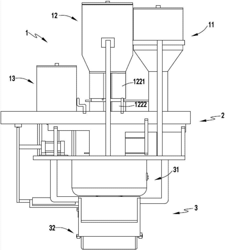
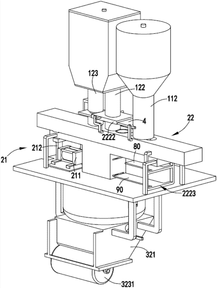
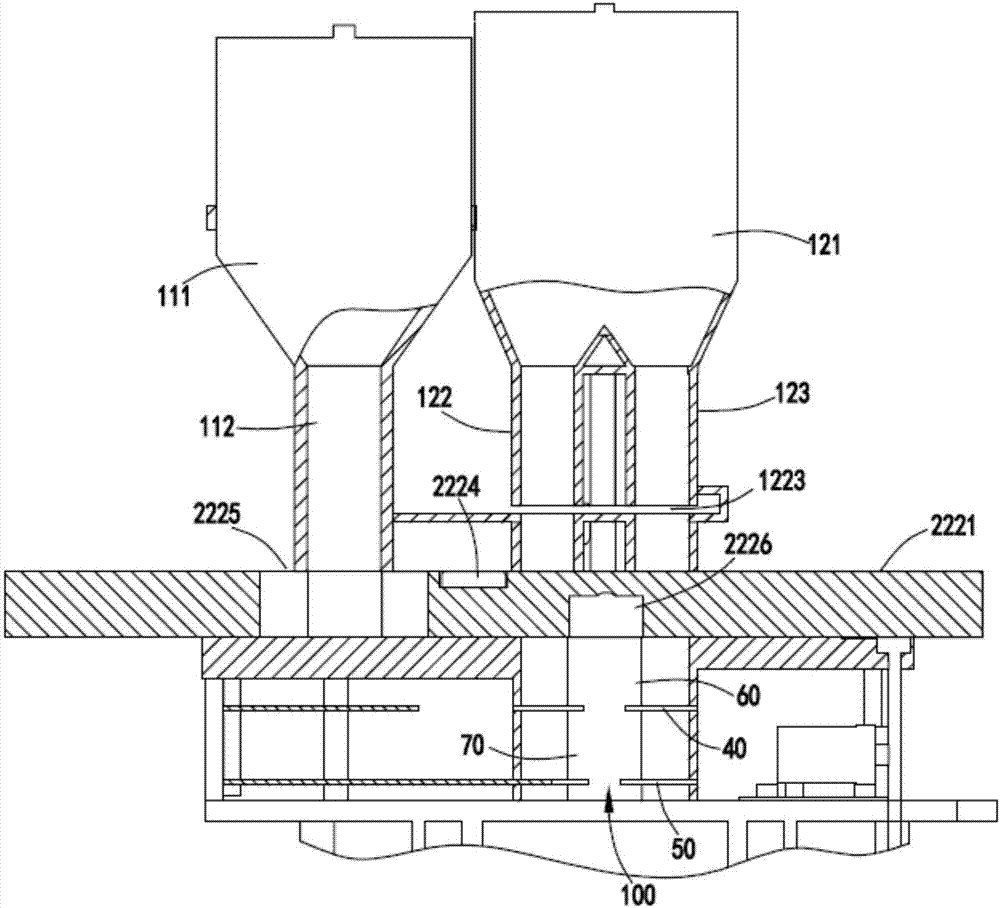
[0051] Such as figure 1 , figure 2 , image 3 , Figure 4 , Figure 5 , Image 6 , Figure 7 , Figure 8 with Figure 9 As shown, an automatic control road marking machine includes a feeding part 1, and the feeding part 1 includes a feeding device a11 for downwardly conveying petroleum resin, a feeding device for downwardly conveying modified rosin resin Device b12 and the feeding device c13 for conveying the powder downward; the batching part 2, the batching part 2 is arranged below the feeding part 1, and the batching part 2 includes a driving mechanism 21 and driven by the driving mechanism 21 A batching mechanism 22 that combines a petroleum resin delivered by the supply device a11 and two modified rosin resins delivered by the supply device b12, and then mixes it with a certain amount of powder; and

[0052] The hot-melt marking part 3, the hot-melt marking part 3 is arranged under the batching part 2, and the hot-melt marking part 3 includes a hot-melt hot-melt ...

Embodiment 2

[0076] Such as figure 1 , figure 2 , image 3 , Figure 4 , Figure 5 , Image 6 , Figure 7 , Figure 8 with Figure 9 As shown, the components that are the same as or corresponding to those in the first embodiment are marked with the corresponding reference numerals in the first embodiment. For the sake of simplicity, only the differences from the first embodiment will be described below. The difference between the second embodiment and the first embodiment is: further, the discharge device 322 is used to control the opening and closing of the discharge hole 3111 provided at the bottom of the hot melt chamber 311, the discharge device 322 includes a bonding heat The control block 3221 on the bottom surface of the melting chamber 311, the slide bar 3222 fixedly connected to one side of the control block 3221 and the slide sleeve 3223 sleeved on the slide bar 3222, the end of the slide sleeve 3223 is connected to the connecting frame 212 fixed connection,

[0077] Su...


PUM


Abstract

The invention relates to an automatic control road marking machine, comprising a feeding part, the feeding part includes a feeding device a for conveying petroleum resin, a feeding device b for conveying modified rosin resin and a feeding device for conveying powder The feeding device c; the batching part, the batching part includes a drive mechanism and a batching mechanism that combines the conveyed petroleum resin and modified rosin resin under the drive of the drive mechanism and mixes it with a certain amount of powder; and hot-melt marking The line part, the hot-melt marking part is arranged under the batching part, and the hot-melt marking part includes a hot-melt mechanism for receiving and melting the mixture and a marking mechanism for coating the paint on the road surface; The invention overcomes the problems that the existing scribing equipment does not have the function of quantitatively proportioning raw materials, a large amount of paint is easily deposited after being melted slowly during use, and the paint ratio is uneven and the scribing effect is poor.

Description

technical field [0001] The invention relates to the technical field of road hot-melt marking equipment, in particular to a mixing equipment for road marking paint. Background technique [0002] Road marking is an important work in the later stage of road construction. Existing road marking machine is mainly made up of car body, wheel and the marking brush that is installed on the car body, when staff pushes car body, marking brush can mark along the traveling route of car body. [0003] The Chinese patent publication number is CN103012937A, and the patent name is a scribing device for scribing lines on the surface of a plate. The scribing device includes a mounting seat and a scribing device. The ink cartridge, the scribing wheel and the outside of the ink cartridge are provided with a fixing seat, the fixing seat is connected with a fixing rod, and both ends of the fixing rod are provided with a mounting seat; a marking device according to the technical solution of the pre...

Claims


Application Information

Patent Timeline
IPC IPC(8): E01C23/24
CPCE01C23/24E01C23/246
Inventor 蒋春生
Owner 长兴小浦凯荣机械加工厂
Learn More