Surface treatment equipment and treatment method for chip capacitor
A surface treatment, chip-type technology, applied in metal processing equipment, grinding/polishing equipment, metal surface removal regulations, etc. Improve work efficiency and performance, not easy to polish scratches and wear, and contribute to human health
- Summary
- Abstract
- Description
- Claims
- Application Information
AI Technical Summary
Problems solved by technology
Method used
Image
Examples
Embodiment 1
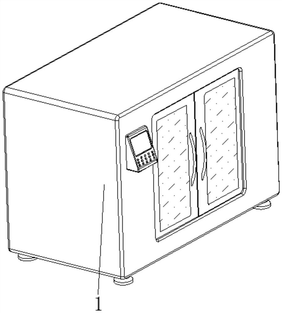
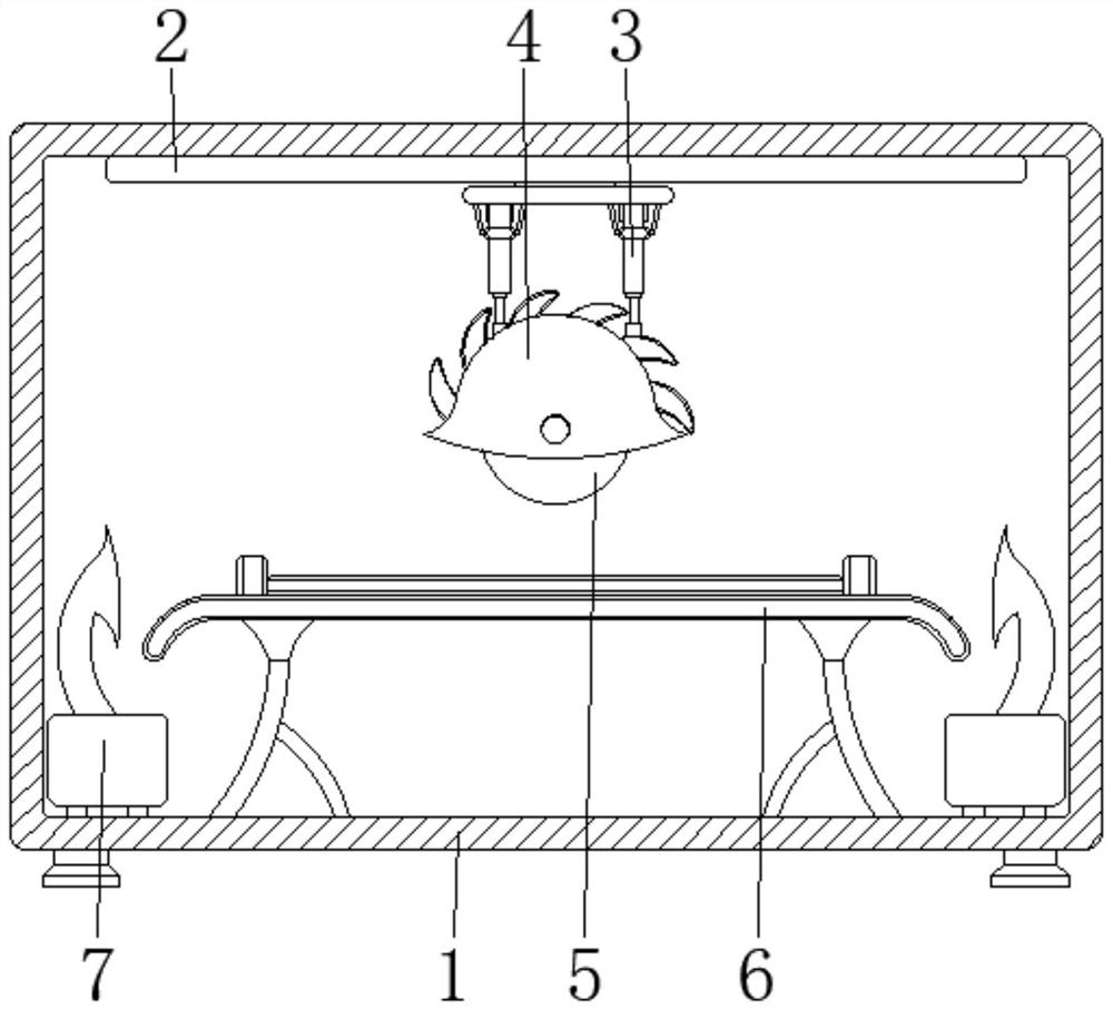
[0035] see Figure 1-6 , the present invention provides a technical solution: a surface treatment equipment for chip capacitors, including a body 1, a linear drive mechanism 2, a lifting mechanism 3, a casing device 4, and a grinding device 5. The linear drive mechanism 2 is arranged on the body 1 The center position of the inner wall top, the lifting mechanism 3 is arranged at the output end of the linear drive mechanism 2, the casing device 4 is arranged at the bottom of the lifting mechanism 3, and the grinding device 5 is arranged inside the casing device 4 and close to the bottom position;
[0036] The central position of the bottom of the inner wall of the body 1 is fixedly connected with a workbench 6, and the bottom of the inner wall of the body 1 and the end near the workbench 6 are all provided with a dust suction mechanism 7, and the chip capacitor device to be polished is fixed on the workbench 6, Reprocess the whole device for preheating, open the lifting mechanis...
Embodiment 2
[0038] The grinding device 5 is provided with a rough grinding roller 51, a fine grinding bar 52, a tension spring 53, a first magnet 54, and a second magnet 55. The rough grinding roller 51 is rotatably connected to the inside of the arc-shaped casing main body 41, and the fine grinding bar 52 slides Connected to the inside of the coarse grinding roller 51 and positioned at the surface position, the tension spring 53 is fixed between the two sides corresponding to the interior of the fine grinding bar 52 and the inside of the rough grinding roller 51, and the first magnet 54 is fixed on the surface of the fine grinding bar 52. side and close to the position of the tension spring 53 , the second magnet 55 is disposed inside the rough grinding roller 51 and close to the position of the first magnet 54 .
[0039] The surface of the coarse grinding roller 51 is provided with a sliding groove compatible with the fine grinding bar 52, and the first magnet 54 and the second magnet 55...
Embodiment 3
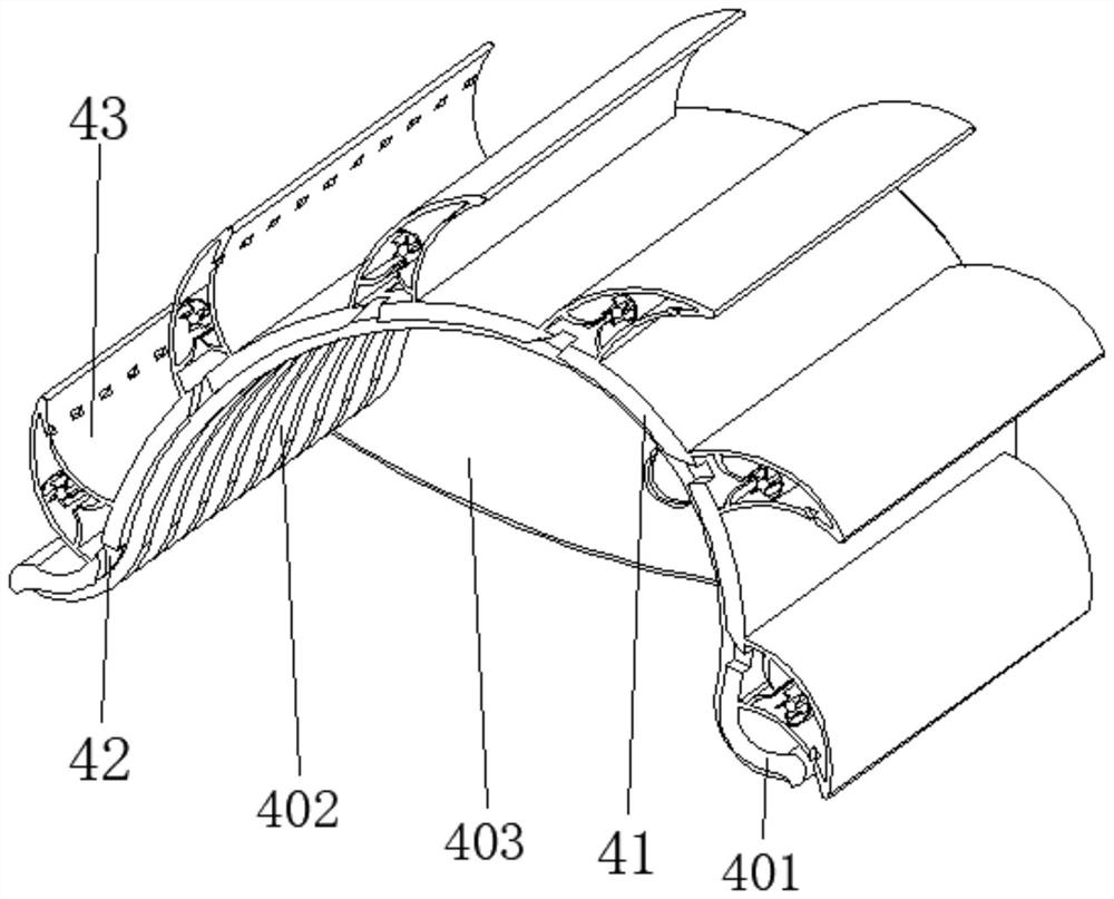
[0041] The casing device 4 is provided with an arc-shaped casing main body 41, a tapered opening 42, and a dust removal device 43. The top of the arc-shaped casing main body 41 is fixedly connected with the bottom of the lifting mechanism 3, and the tapered opening 42 is opened on the curved casing main body. 41, the dust removal device 43 is arranged on the top of the arc-shaped casing main body 41 and close to the tapered opening 42;
[0042] The dust removal device 43 is provided with a horn housing 431, an arc guide assembly 432, a filter screen 433, a cleaning device 434, and an air outlet opening 435. The bottom of the horn housing 431 is fixedly connected with the top of the arc-shaped casing main body 41, and the arc guide The flow assembly 432 is fixed on the inner wall of the horn housing 431 and near the tapered opening 42, the filter screen 433 is fixed on the inner wall of the horn housing 431, and the cleaning device 434 is arranged inside the horn housing 431 and...
PUM
 Abstract
Description
Claims
Application Information
 - R&D
- Intellectual Property
- Life Sciences
- Materials
- Tech Scout
- Unparalleled Data Quality
- Higher Quality Content
- 60% Fewer Hallucinations
Browse by: Latest US Patents, China's latest patents, Technical Efficacy Thesaurus, Application Domain, Technology Topic, Popular Technical Reports.
© 2025 PatSnap. All rights reserved.Legal|Privacy policy|Modern Slavery Act Transparency Statement|Sitemap|About US| Contact US: help@patsnap.com


