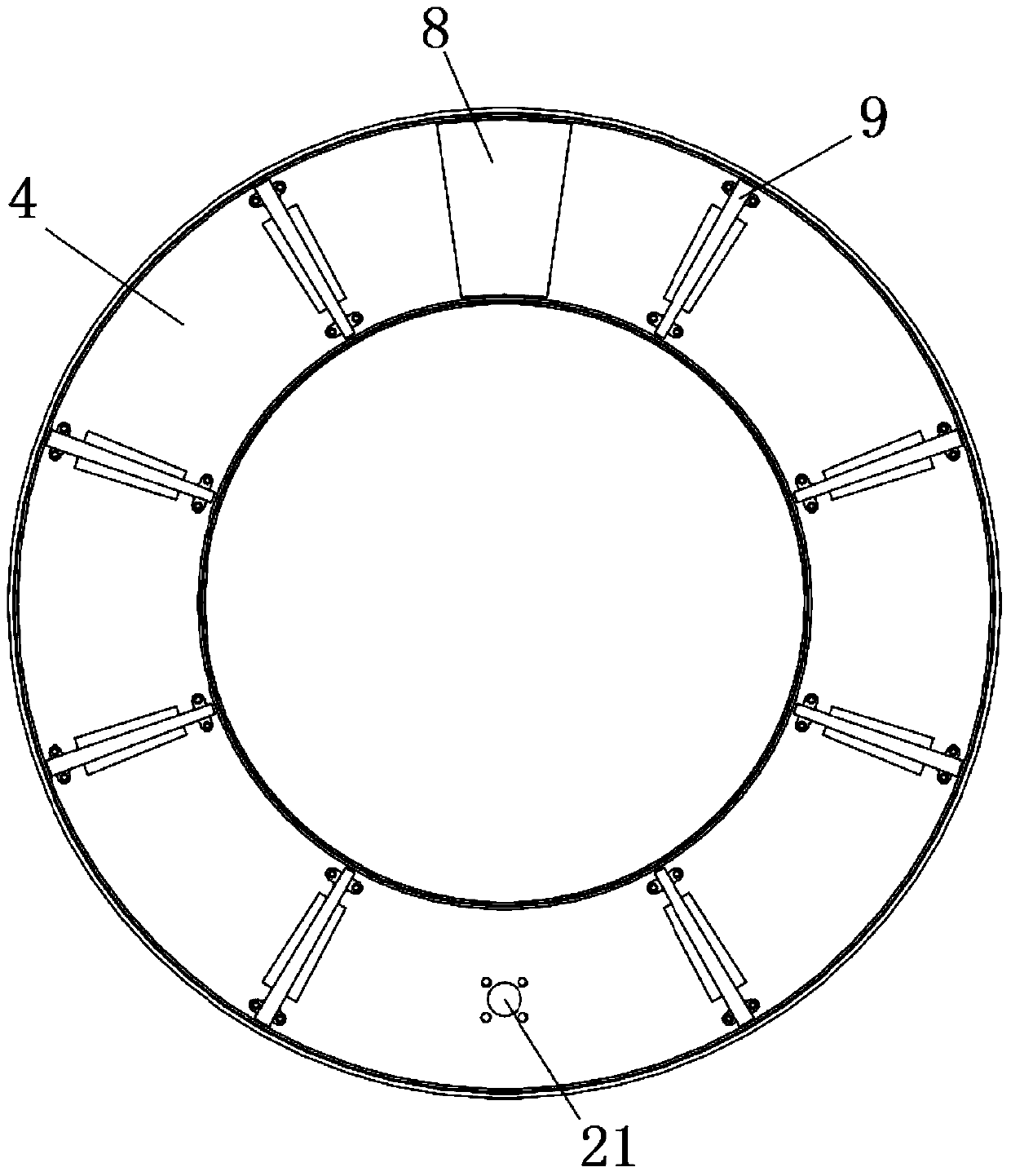
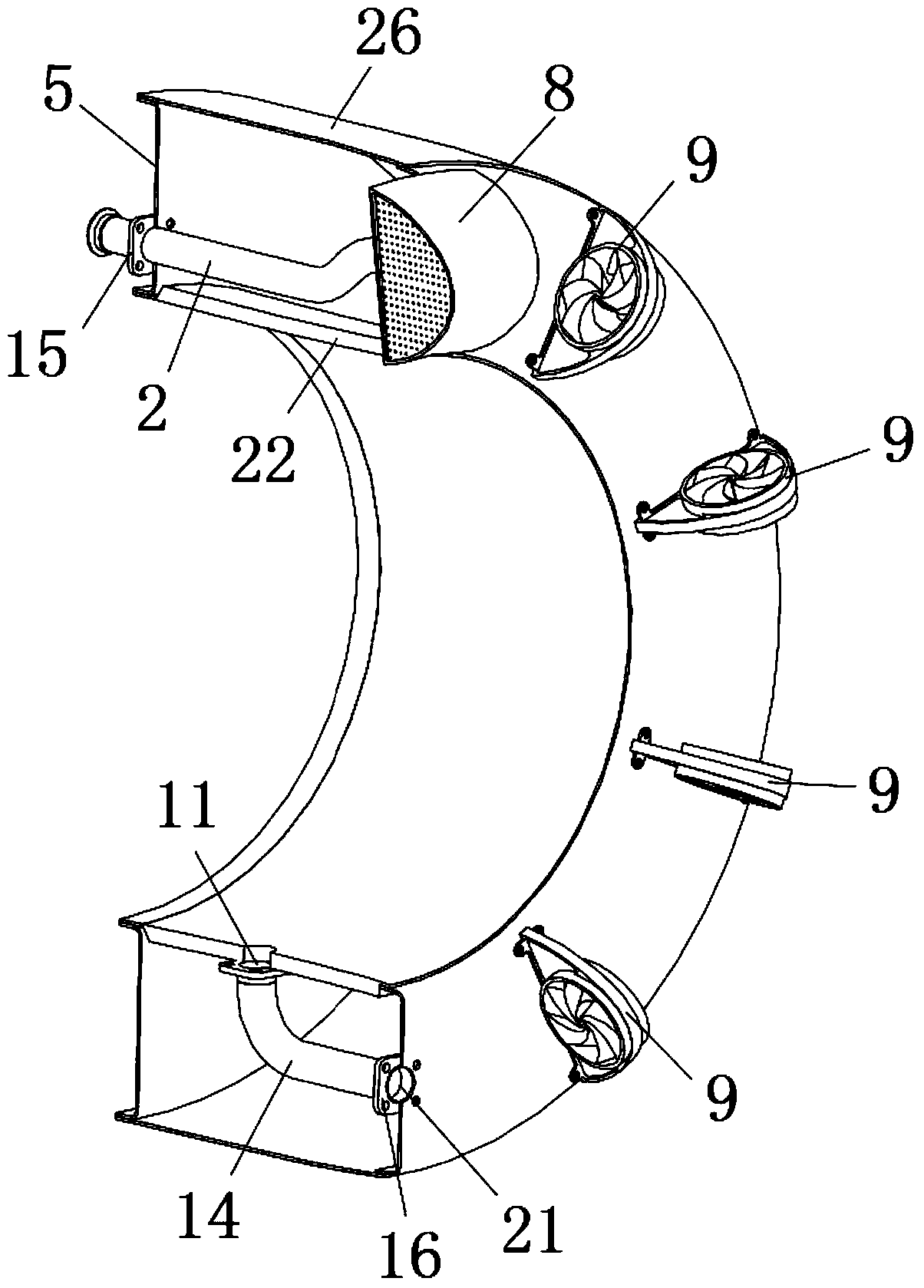
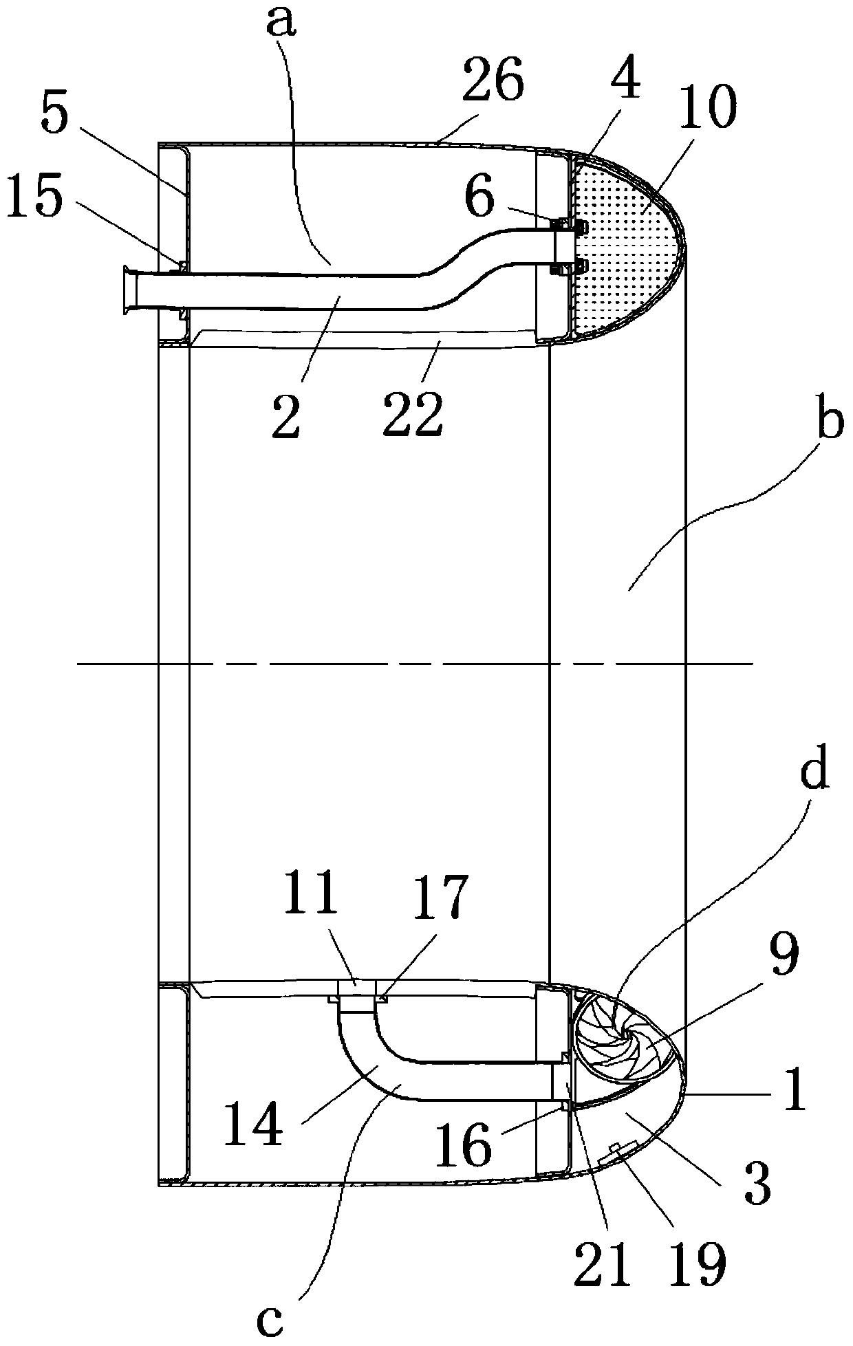
Engine gas inlet pipe anti-icing system and aircraft engine

An anti-icing system and air intake technology, which is applied in the direction of machines/engines, mechanical equipment, jet propulsion devices, etc., can solve problems such as unsatisfactory, high temperature, uncontrollable flow direction and speed of hot air, etc., to improve anti-icing efficiency, The effect of improving heat exchange efficiency and reducing the amount of bleed air

Active Publication Date: 2016-04-20
AECC COMML AIRCRAFT ENGINE CO LTD
View PDF7 Cites 6 Cited by
  • Summary
  • Abstract
  • Description
  • Claims
  • Application Information

AI Technical Summary

Problems solved by technology

[0003] The usual hot gas anti-icing device directly draws air from the high-pressure compressor, flows through the control valve, allows the hot air to flow freely in the heat exchange channel at the front edge of the intake port, and finally discharges from the discharge port, or adopts a ring-shaped air injection pipeline. Make some small holes on the road, and fix them on the front ballast wall of the nacelle through brackets. The hot air passes through the small holes on the pipeline and sprays the hot air in a certain direction to the anti-icing surface to play the role of anti-icing. Directional jet airflow can easily cause local high temperature on the anti-icing surface. Therefore, no matter what kind of anti-icing device mentioned above, there are problems such as unadjustable bleed air volume and uncontrollable flow direction and speed of hot air in the heat exchange channel, resulting in uncontrollable heat exchange efficiency. , and there is a possibility that the internal structure of the intake port may be burned or the anti-icing effect may be unsatisfactory due to too large or too small amount of bleed air

Method used


Image

  • Engine gas inlet pipe anti-icing system and aircraft engine
  • Engine gas inlet pipe anti-icing system and aircraft engine
  • Engine gas inlet pipe anti-icing system and aircraft engine

Examples


Embodiment Construction

[0037] Below will combine the appended in the embodiment of the present invention Figure 1-10 , clearly and completely describe the technical solutions in the embodiments. Apparently, the described embodiments are only some of the embodiments of the present invention, not all of them. Based on the embodiments of the present invention, all other embodiments obtained by persons of ordinary skill in the art without creative efforts fall within the protection scope of the present invention.

[0038] In describing the present invention, it is to be understood that the terms "central", "longitudinal", "transverse", "front", "rear", "left", "right", "vertical", "horizontal", The orientation or positional relationship indicated by "top", "bottom", "inner", "outer" and so on may be based on the orientation or positional relationship shown in the drawings, which are only for the convenience of describing the present invention and simplifying the description, rather than indicating or ...


PUM


Abstract

The present invention relates to an engine gas inlet pipe anti-icing system and an aircraft engine. The engine gas inlet pipe anti-icing system comprises a gas introduction structure, a heat exchange structure and a gas discharge structure, wherein a plurality of diversion devices are arranged inside the heat exchange structure, hot gas introduced by the gas introduction structure enters the heat exchange structure, diversion is performed through the diversion devices inside the heat exchange structure so as to make the hot gas helically advance in the heat exchange structure, and after the heat exchange, the obtained gas is discharged through the gas discharge structure. According to the present invention, the diversion devices are arranged to perform diversion on the introduced hot gas to adjust the hot gas flowing direction, such that the hot gas helically advances in the heat exchange structure so as to accelerate the heat exchange between the hot gas and the anti-icing surface, improve the heat exchange efficiency inside the heat exchange structure, and reduce the anti-icing gas introduction amount.

Description

technical field [0001] The invention relates to the field of aero-engines, in particular to an anti-icing system for an engine intake passage and an aero-engine. Background technique [0002] There is a possibility of air intake icing in aero-engines flying at high altitude or under ground conditions. Air-inlet icing is the most dangerous situation in aircraft icing. It not only directly leads to damage to the aerodynamic shape of the air intake, but also reduces the The thrust will increase the flight load, and when the ice layer in the air intake falls off, it will enter the engine with the airflow, damage the fan blades with a high speed, cause mechanical damage to the compressor, and even damage the entire engine, directly triggering flight. ACCIDENT. Therefore, in order to ensure flight safety, engine anti-icing is very important, and it is necessary to realize the de-icing or anti-icing function through the air inlet anti-icing device. At present, the heat source for...

Claims


Application Information

Patent Timeline
Patent Type & Authority Applications(China)
IPC IPC(8): F02C7/047
Inventor 刘永岳腾
Owner AECC COMML AIRCRAFT ENGINE CO LTD
Why Eureka
Try Eureka