Method and device for processing based on layer
A processing method and layer technology, applied in the direction of electrical digital data processing, special data processing applications, geographic information databases, etc., can solve problems such as not paying attention to the communication field, achieve rich graphic display effects, simple implementation, and high flexibility Effect
- Summary
- Abstract
- Description
- Claims
- Application Information
AI Technical Summary
Problems solved by technology
Method used
Image

Examples
Embodiment 1
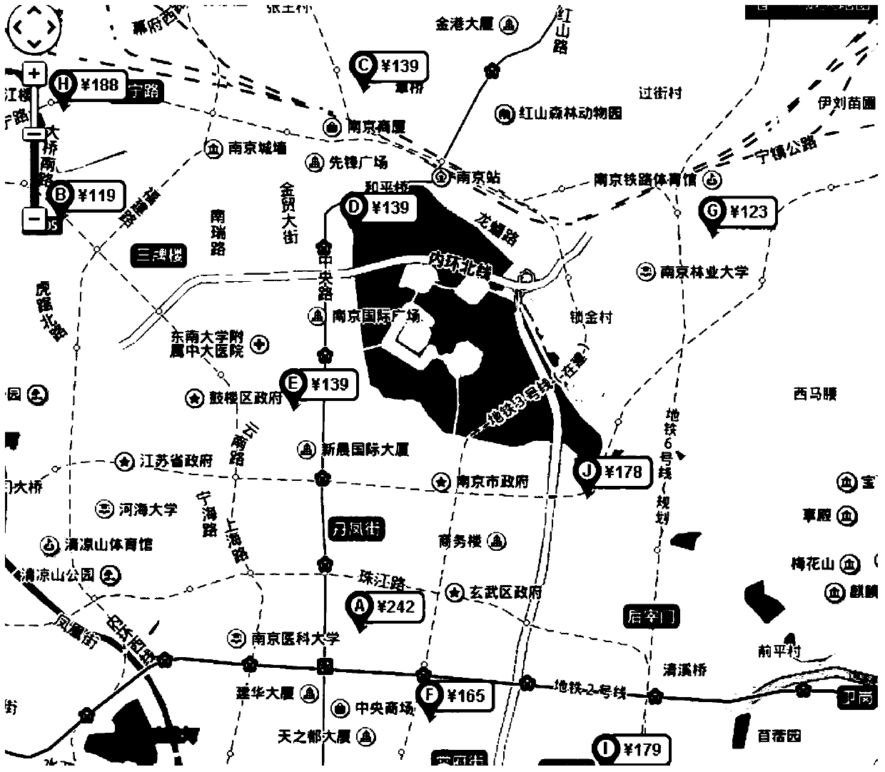
[0079] GIS software focuses on the processing related to geographic location information, and also mainly renders geographic elements when drawing, such as location identification, routes, etc. For the network management in the communication industry, regardless of whether GIS maps are used or not, the performance drawing of the network management is the most important. The presentation of alarms and status needs to be known at a glance in the topology. However, GIS has penetrated into all walks of life, and network management will gradually use many GIS functions to improve network management operability and ease of use. Since the GIS software has different concerns, this embodiment combines the rich rendering effects of the network management system with the powerful GIS functions, so that the GIS functions are not missing and the rich rendering effects of the network management system are still retained.
[0080] In order to overcome the shortcomings of GIS software drawing...
PUM
 Abstract
Description
Claims
Application Information
PatSnap Eureka turns technology decisions into work you can execute. Powered by our Innovation Knowledge Graph, it runs expert workflows across engineering, life sciences, materials and intellectual property. Get your review-ready output in minutes.


