
Object internal heat source distribution and reconstruction system and method

A technology of internal heat sources and objects, applied in the field of heat transfer, can solve problems such as hindering applications, very strict requirements, and unsatisfactory inversion results, etc., to simplify the reconstruction process, universal practical value, and avoid regularization processing process and boundary conditions to deal with the effect of the process

Active Publication Date: 2016-04-20
GUANGZHOU BRIGHT MEDICAL TECH
View PDF3 Cites 5 Cited by
  • Summary
  • Abstract
  • Description
  • Claims
  • Application Information

AI Technical Summary

Problems solved by technology

The currently reported methods mainly include conjugate gradient method, boundary element method, finite element method and finite volume method, etc. These methods have certain advantages in the inversion of the geometric distribution of heat sources inside objects and the intensity of heat sources, but they always face three problems. There are two unsolvable problems: 1. Inversion can only be performed on point heat sources or spherical heat sources. If the shape of the heat source changes, the inversion results are not ideal; 2. The requirements for the shape of objects are very strict, such as the boundary element method, Often only objects with regular shapes can invert better results; 3. The handling of boundary conditions is extremely harsh
The above three points seriously hinder the application of these methods in actual thermal engineering, because for actual objects, such as mechanical units, nuclear waste, grain piles, and even certain parts or organs of the human body, the internal heat source and external shape are often Irregular, and some boundary data are also difficult to obtain

Method used


Image

  • Object internal heat source distribution and reconstruction system and method
  • Object internal heat source distribution and reconstruction system and method
  • Object internal heat source distribution and reconstruction system and method

Examples


Embodiment Construction

[0020] In order to make the object, method, technical solution and advantages of the present invention clearer, the present invention will be further described in detail below in conjunction with the accompanying drawings. It should be understood that the description herein is only used to explain the present invention, not to limit the present invention.

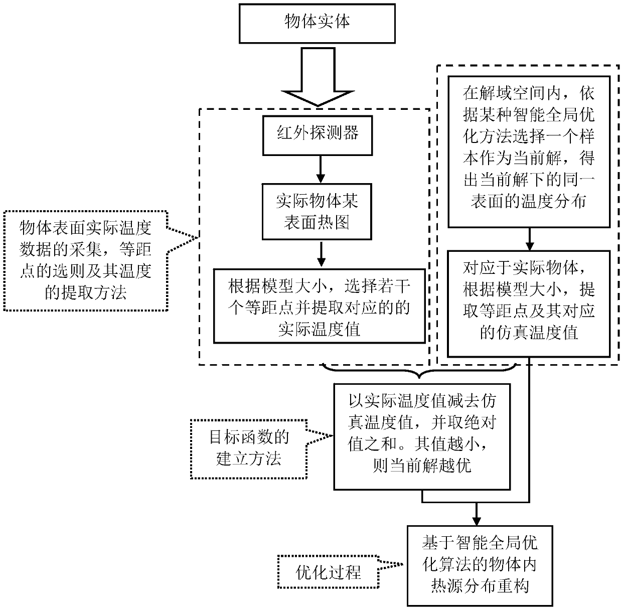
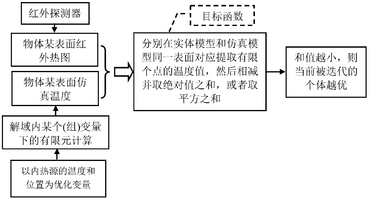
[0021] Deriving the internal heat source distribution from the surface temperature of an object is a typical heat conduction inverse problem. This invention takes the temperature and position of the internal heat source of the object as optimization variables, and based on an intelligent global optimization algorithm, converts this complex heat conduction inverse problem into a direct problem for solution. , which avoids the complex boundary condition processing and regularization processing in the current common methods.

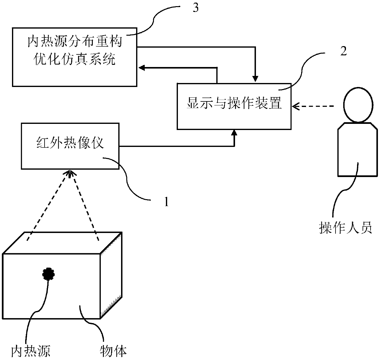
[0022] figure 1 It is a structural schematic diagram of a system and method for reconstructing heat ...


PUM


Abstract

The invention relates to an object internal heat source distribution and reconstruction system and method. The method includes: using the temperature T and position P (x, y and z) of an object internal heat source as optimization variables, and acquiring the temperature information and position information of the object internal heat source on the basis of an intelligent global optimization algorithm. The system mainly comprises an infrared thermal imager, an internal heat source distribution and reconstruction optimization simulation system and a display and operation device, wherein the infrared thermal imager is connected with the display and operation device, and the display and operation device is connected with the internal heat source distribution and reconstruction optimization simulation system. By the object internal heat source distribution and reconstruction system and method with wide actual application value, object internal heat source distribution and reconstruction efficiency is increased.

Description

technical field [0001] The invention relates to the technical field of heat transfer, in particular to a system and method for reconfiguring the distribution of heat sources in an object. Background technique [0002] In the field of thermal engineering applications, the state of the heat source inside the object, or the thermal state of a certain part or part inside the object is very important to master and understand its operation. The identification of internal heat source parameters based on external temperature measurement is widely used in actual production and daily life, such as some long-term fixed substances with internal heat sources, such as generator sets in hydroelectric dams, nuclear waste, coal and food, etc. Once there is a problem with its internal operation or improper storage, it will generate heat. In many cases, it is very difficult or even impossible to measure the internal temperature of an object. Therefore, the method of accurately and quickly det...

Claims


Application Information

Patent Timeline
Patent Type & Authority Applications(China)
IPC IPC(8): G06F17/50
CPCG06F30/23
Inventor 史贵连叶福丽
Owner GUANGZHOU BRIGHT MEDICAL TECH
Learn More