Compound auxiliary winding TiBuck-Flyback single-stage LED driving circuit

A LED drive and auxiliary winding technology, applied in the direction of electric light source, electrical components, electroluminescent light source, etc., can solve the problems of increasing the cost of LED driver, affecting the efficiency of the driver, and large output current ripple, etc., to achieve superior input characteristics, System cost reduction, effect of reducing low-frequency ripple

Inactive Publication Date: 2016-04-20
FUZHOU UNIV
View PDF4 Cites 21 Cited by
  • Summary
  • Abstract
  • Description
  • Claims
  • Application Information

AI Technical Summary

Problems solved by technology

The two-stage PFC scheme has the advantages of small total harmonic distortion (THD) and close to unity value of power factor (PF), but the two-stage conversion means that more main power devices and control ICs are used, which increases the LED driver. The cost also affects t

Method used


Image

  • Compound auxiliary winding TiBuck-Flyback single-stage LED driving circuit
  • Compound auxiliary winding TiBuck-Flyback single-stage LED driving circuit
  • Compound auxiliary winding TiBuck-Flyback single-stage LED driving circuit

Examples


Embodiment Construction

[0028] The present invention will be further described below in conjunction with the accompanying drawings and embodiments.

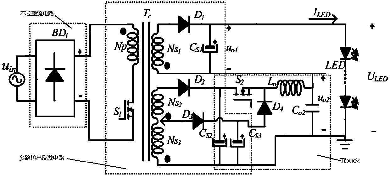
[0029] Such as figure 1 As shown, this embodiment provides a composite auxiliary winding TiBuck-Flyback single-stage LED drive circuit, including an uncontrolled rectification circuit, a multi-output flyback circuit, and a TiBuck circuit, specifically including an input power supply u in , rectifier bridge BD 1 , Transformer T r , Power MOS switch tube S 1 , Power MOS switch tube S 2 , power diode D 1 , power diode D 2 , power diode D 3 , power diode D 4 , electrolytic capacitor Cs 1 , electrolytic capacitor Cs 2 , electrolytic capacitor Cs 3 , output capacitance Co 2 , output inductance L o , output load LED; the rectifier bridge BD 1 The positive output terminal of the transformer is connected to T r The same name terminal of the primary side; the transformer T r The non-identical end of the primary side is connected to the power MOS sw...


PUM


Abstract

The invention relates to a compound auxiliary winding TiBuck-Flyback single-stage LED driving circuit which comprises an input power supply uin, a rectifier bridge BD1, a transformer Tr, a power metal oxide semiconductor (MOS) switching tube S1, a power MOS switching tube S2, a power diode D1, a power diode D2, a power diode D3, a power diode D4, an electrolytic capacitor Cs1, an electrolytic capacitor Cs2, an electrolytic capacitor Cs3, an output capacitor Co2, an output inductor Lo and an output load LED. By construction of the single-stage auxiliary TiBuck-Flyback compound LED driving circuit and a self-adaption control circuit thereof, functions such as efficient, low-ripple and constant current output are achieved.

Description

technical field [0001] The invention relates to the field of driving power supply design, in particular to a composite auxiliary winding TiBuck-Flyback single-stage LED driving circuit. Background technique [0002] LED is essentially a light-emitting diode, and its volt-ampere characteristics determine that it is suitable for constant current operation. For the design of the drive power supply, it is first necessary to select an appropriate circuit structure. According to different application occasions and requirements, it can generally be divided into single-stage scheme and two-stage structure scheme, both of which have their own advantages and disadvantages according to the application power occasion and specific application requirements. The two-stage PFC scheme has the advantages of small total harmonic distortion (THD) and close to unity value of power factor (PF), but the two-stage conversion means that more main power devices and control ICs are used, which increa...

Claims


Application Information

Patent Timeline
IPC IPC(8): H05B33/08H05B44/00
CPCH05B45/37Y02B20/30
Inventor 林维明吴南冰李银宝
Owner FUZHOU UNIV
Why Eureka
Try Eureka