Connection structure between transmission shaft and vehicle body of a front-rear drive vehicle

A technology of front and rear drive and connection structure, which is applied in the direction of control devices, vehicle parts, transportation and packaging, etc., which can solve the problem of high strength and rigidity performance requirements of the connection structure, complex structure of the bracket assembly of the body assembly, and unfavorable light weight Vehicle cost control and other issues, it is easy to meet the stiffness performance requirements, improve fuel economy, and improve NVH performance

Active Publication Date: 2018-01-02
CHONGQING CHANGAN AUTOMOBILE CO LTD
View PDF16 Cites 0 Cited by
  • Summary
  • Abstract
  • Description
  • Claims
  • Application Information

AI Technical Summary

Problems solved by technology

This connection structure has the following problems: (1) The drive shaft is installed in the support frame of the drive shaft, the support frame of the drive shaft is installed on the bracket assembly of the body assembly, and the bracket assembly of the body assembly is installed on the connecting bracket of the body body. The rotation center of the shaft is far away from the car body, which requires high strength and rigidity performance of the connecting structure; (2) The connection between the transmission shaft and the car body needs to be realized with the help of the body assembly bracket assembly, and the body assembly bracket assembly The structure is complex and heavy, and the cost is high, which is not conducive to the realization of lightweight body structure and vehicle cost control

Method used


Image

  • Connection structure between transmission shaft and vehicle body of a front-rear drive vehicle
  • Connection structure between transmission shaft and vehicle body of a front-rear drive vehicle
  • Connection structure between transmission shaft and vehicle body of a front-rear drive vehicle

Examples


Embodiment Construction

[0019] The present invention will be described in detail below in conjunction with the accompanying drawings.

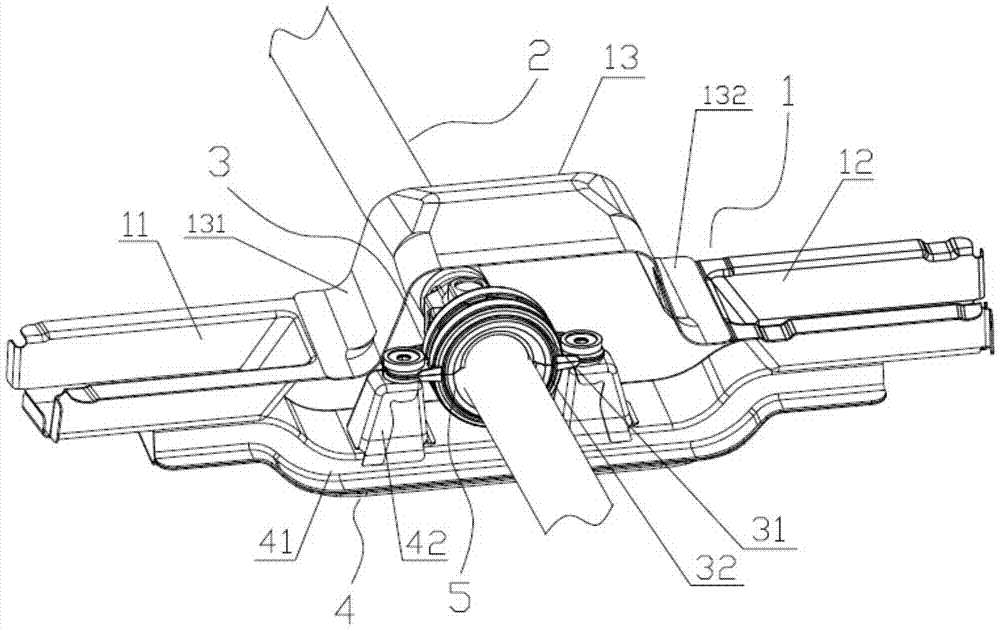
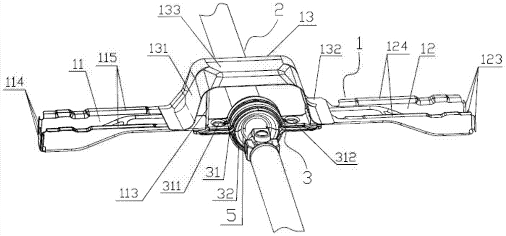
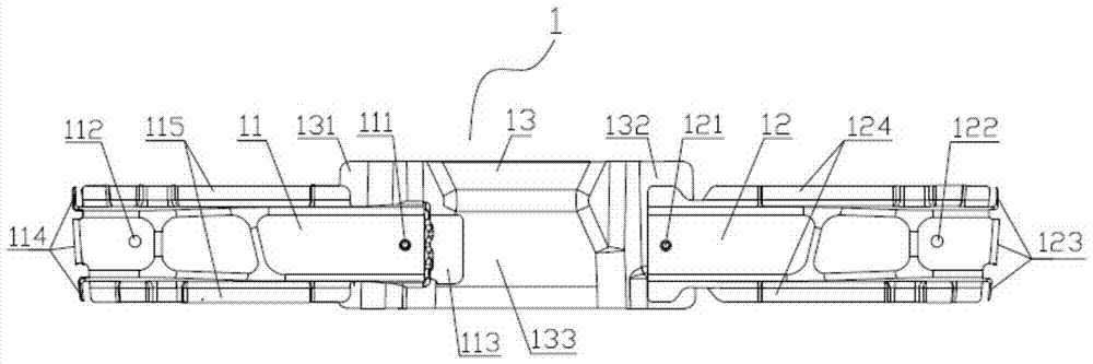
[0020] Such as Figure 2 to Figure 5 The connection structure between the drive shaft and the vehicle body of the front-rear drive vehicle shown includes the body main body connection bracket 1 and the transmission shaft support frame 3. Shaped left mounting beam 11 and a U-shaped right mounting beam 12 in section form. The outer surface of the left flange 131, the outer surface of the top 133 and the outer surface of the right flange 132 of the "J"-shaped structure of the crossbeam connector 13 are welded to the front floor channel.

[0021] The left end of the left mounting beam 11 has a first left welding flange 114 welded with the left longitudinal beam of the vehicle body, and the upper front and rear sides of the left mounting beam 11 have a second left welding flange 115 welded with the left floor panel. The right end of the second left welding flange 115 of...


PUM


Abstract

The invention discloses a connecting structure for a transmission shaft and a vehicle body of a rear-wheel-drive vehicle with a front-mounted engine, comprising a main body connecting bracket of the vehicle body and a support frame of the transmission shaft, wherein the main body connecting bracket of the vehicle body is formed by welding a cross beam connecting piece, a left mounting cross beam and a right mounting cross beam; the bottom surface of the left mounting cross beam is a second-grade step surface, and the second-stage step surface close to the right end is provided with a left mounting hole and is welded with a projection welding nut; the bottom surface of the right mounting cross beam is a second-grade step surface, and the second-stage step surface close to the left end is provided with a right mounting hole and is welded with a projection welding nut; the left end of the support frame of the transmission shaft is provided with a left connecting hole, and the right end of the support frame of the transmission shaft is provided with a right connecting hole; and the transmission shaft is mounted in the support frame of the transmission shaft through a lining, and the support frame of the transmission shaft is mounted on the main body connecting bracket of the vehicle body through matching between bolts and the left connecting hole, the left mounting hole, the right connecting hole, the right mounting hole as well as the projection welding nuts. The connecting structure can enable the vehicle body structure to be light and can more easily meet strength and stiffness requirements.

Description

technical field [0001] The invention relates to a car body structure, in particular to a connection structure between a drive shaft and a car body of a front-rear drive car. Background technique [0002] The drive shaft of a front-rear drive vehicle is the key structure that undertakes the power transmission of the vehicle, and it is also the key factor that affects the comfort indicators such as NTF (noise transfer function) and VTF (vibration transfer function) of the vehicle, as well as power economy indicators such as power transmission. The key system structure, in order to meet its performance requirements, the connection structure between the transmission shaft and the vehicle body (that is, the installation structure of the transmission shaft) is often designed to be relatively bulky. [0003] Such as figure 1 As shown, the existing connection structure between the transmission shaft and the vehicle body includes the vehicle body main body connection bracket 1, the ...

Claims


Application Information

Patent Timeline
Patent Type & Authority Patents(China)
IPC IPC(8): B60K17/24
CPCB60K17/24
Inventor 胡军
Owner CHONGQING CHANGAN AUTOMOBILE CO LTD
Why Eureka
Try Eureka