Installation structure and method for washing machine display screen
A technology of installation structure and installation method, which is applied in the field of washing machines, can solve the problems of complex installation methods and single application range of display screens, and achieve the effects of being suitable for popularization and use, simplifying the process, and improving reliability and service life
- Summary
- Abstract
- Description
- Claims
- Application Information
AI Technical Summary
Problems solved by technology
Method used
Image
Examples
Embodiment 1
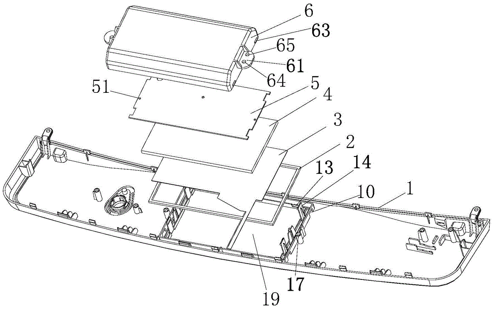
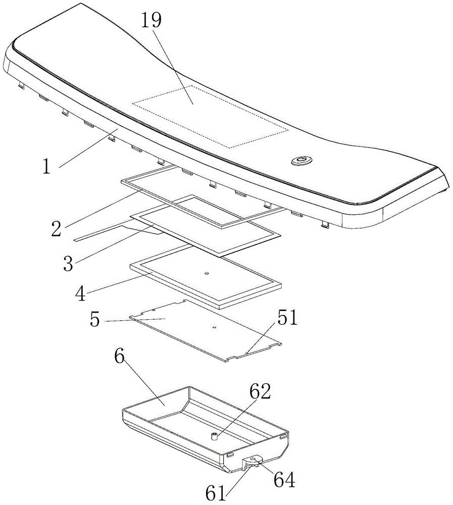
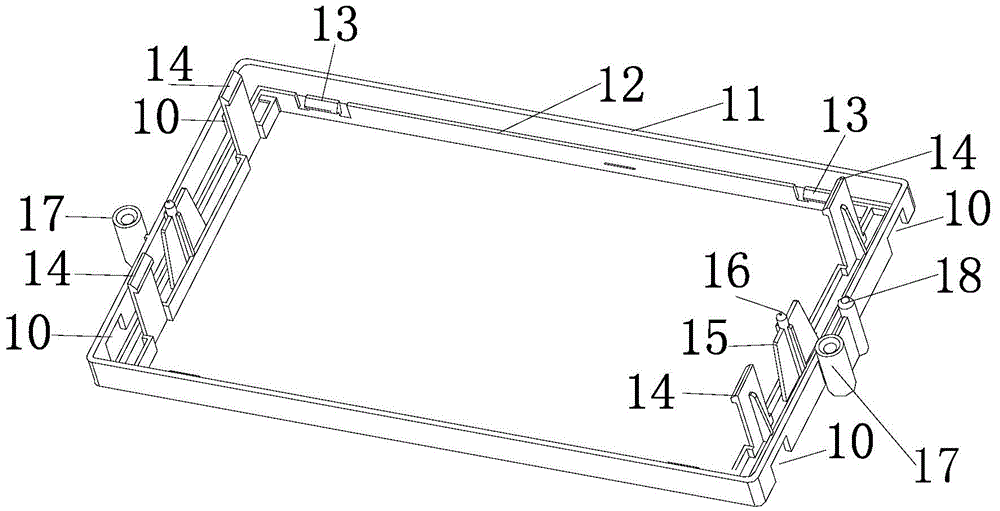
[0063] In this embodiment, the hollow part of the installation frame 12 is provided with a display screen 4, and at least one first claw 13 is respectively provided on a pair of opposite side walls of the installation frame 12, and the first claw 13 holds the display screen 4 is fixedly installed in the installation frame 12.
[0064] Such as Figure 1 to Figure 4 As shown, in this embodiment, the display screen 4 is square, and the shape of the installation frame 12 is the same as that of the display screen 4 . A pair of opposite side walls of the square mounting frame 12 are respectively provided with two first claws 13, and the first claws 13 are respectively arranged at the ends close to the corresponding side walls; the first claws 13 on the two side walls are opposite to each other. The axis of the display screen 4 is arranged symmetrically.
[0065] In this embodiment, the first claw 13 includes a shrapnel, one end of the shrapnel is connected to the control panel 1 ,...
Embodiment 2
[0067] Such as Figure 1 to Figure 3 As shown, in this embodiment, at least one pair of opposite side walls of the packaging support frame 11 is respectively provided with at least one screw column 17, and the screw column 17 is respectively fixed with the sealing cover 6 through bolt connection.
[0068] The package support frame 11 is a square shape matching the display screen 4, and a pair of opposite side walls of the square package support frame 11 are respectively provided with a screw column 17, and the screw column 17 is arranged on the corresponding side wall. middle part. The outer periphery of the sealing cover 6 is provided with a mounting rib 61 corresponding to the screw column 17, and the described mounting rib 61 is provided with a bolt hole 62 matched with the screw column 17, and the bolt connects the above screw column 17 and The bolt holes 62 are matched with threaded connections, so that the sealing cover 6 and the control panel 1 are fixed through the ab...
Embodiment 3
[0075] In this embodiment, the driving circuit of the display screen 4 is separately provided to form the driving board 5 . The driving board 5 is arranged between the sealing cover 6 and the display screen 4 , and the driving board 5 is fixedly connected with the control panel 1 . The driving board 5 is electrically connected with the display screen 4 . The drive board 5 is provided with a drive circuit to realize the touch control and display functions of the display screen 4 .
[0076] Such as Figure 1 to Figure 4 As shown, in this embodiment, the installation frame 12 is a square shape matching the display screen 4, and at least one second claw 14 is respectively provided on a pair of opposite side walls of the square installation frame 12; preferably, the square installation A pair of opposite side walls of the frame 12 are respectively provided with two second claws 14 disposed near the ends of the corresponding side walls, and the second claws 14 on the two side wall...
PUM
 Abstract
Description
Claims
Application Information
 - R&D
- Intellectual Property
- Life Sciences
- Materials
- Tech Scout
- Unparalleled Data Quality
- Higher Quality Content
- 60% Fewer Hallucinations
Browse by: Latest US Patents, China's latest patents, Technical Efficacy Thesaurus, Application Domain, Technology Topic, Popular Technical Reports.
© 2025 PatSnap. All rights reserved.Legal|Privacy policy|Modern Slavery Act Transparency Statement|Sitemap|About US| Contact US: help@patsnap.com


