Twin turbo engine

A turbocharger and turbocharger technology, applied in engine components, combustion engines, machines/engines, etc., to solve problems such as difficulty in controlling exhaust gas return, expensive exhaust flap valves, and unused exhaust energy.

Active Publication Date: 2016-04-27
FORD GLOBAL TECH LLC
View PDF6 Cites 4 Cited by
  • Summary
  • Abstract
  • Description
  • Claims
  • Application Information

AI Technical Summary

Problems solved by technology

[0007] Problems when using sequential twin turbochargers may include the control of torque fluctuations and corresponding power fluctuations during activation or deactivation of the second turbocharger, and for activation or deactivation of the second turbocharger Expensive flap v...

Method used


Image

  • Twin turbo engine
  • Twin turbo engine
  • Twin turbo engine

Examples


Embodiment Construction

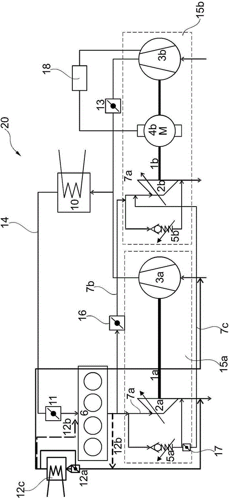
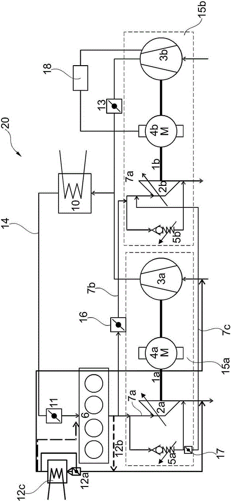
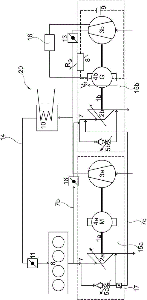
[0016] like figure 1 As shown, the invention relates to an arrangement of an internal combustion engine having a first turbocharger and a second turbocharger, wherein at least the second turbocharger additionally has an electrical energy converter. like Figure 2 to Figure 4 As shown, the first turbocharger may also include a separate electric energy converter, wherein the separate electric energy converter can be operated in a motor mode or a generator mode. exist Figure 5 A method of operating these power converters based on exhaust gas flow and / or battery state of charge is shown in .

[0017] In a first embodiment, an internal combustion engine for a motor vehicle may include a first turbocharger and a second turbocharger, the first turbocharger including at least a first turbine and at least a first compressor , the second turbocharger has at least a second turbine and at least a second compressor. The first turbocharger and the second turbocharger may be arranged in...


PUM


Abstract

Es wird eine Anordnung einer Brennkraftmaschine mit einem sequentiellparallelen Zwillingsturbolader bereitgestellt, bei der mindestens ein Turbolader einen elektrischen Energiewandler aufweist, der wahlweise als Motor zum Antrieb eines Verdichters im unteren Drehzahlbereich der Brennkraftmaschine oder als Generator zum Aufladen einer angeschlossenen Batterie verwendet werden kann. Weiterhin wird ein Verfahren unter Verwendung der Anordnung bereitgestellt.

Description

[0001] Cross References to Related Applications [0002] This application claims priority from German Patent Application No. 102014221333.9 filed on October 21, 2014, which is hereby incorporated by reference in its entirety for all purposes. technical field [0003] The present description generally relates to methods and systems of controlling at least a first electrical energy converter of a vehicle. Background technique [0004] A turbocharger may provide compressed combustion air to one or more cylinders of an internal combustion engine. A turbocharger includes a turbine and a compressor, both of which may be of similar construction and mounted on a joint shaft. The mass flow of the exhaust may rotate a turbine wheel in the turbine to turn the compressor. Torque is transmitted via the engagement shaft to the compressor wheel in the intake duct, as a result of which the compressor compresses the combustion air. [0005] As long as enough exhaust gas is flowing into th...

Claims


Application Information

Patent Timeline
IPC IPC(8): F02B37/10F02B37/007F02B39/10
CPCF01N5/04F02B37/002F02B37/007F02B37/18F02M26/08F02B37/10F02B37/004Y02T10/12
Inventor H·施托费尔斯L·斯塔姆普C·韦伯
Owner FORD GLOBAL TECH LLC
Why Eureka
Try Eureka