Liquid separator
A liquid separator and filter bracket technology, which is applied in refrigeration and liquefaction, refrigeration components, refrigerators, etc., can solve problems such as compressor abnormal shock, compressor liquid shock, exhaust pipe shock, etc., to prevent liquid shock Occurrence, reduction of liquid hammer phenomenon, and improvement of reliability
- Summary
- Abstract
- Description
- Claims
- Application Information
AI Technical Summary
Problems solved by technology
Method used
Image
Examples
Embodiment 1
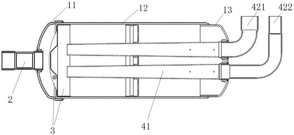
[0034] Such as figure 1 , figure 2 and image 3 As shown, this embodiment provides a liquid dispenser, specifically, the liquid dispenser includes a cylinder body, a suction pipe 2, a filter assembly 3 and at least two exhaust pipes. Wherein, the cylinder includes an upper cylinder 11 , a middle cylinder 12 and a lower cylinder 13 . The suction pipe 2 is connected to the top end of the cylinder (that is, the suction pipe 2 is connected to the end of the upper cylinder 11 ), and is used to transport the refrigerant into the cylinder. The filter screen assembly 3 is arranged in the cylinder, preferably located in the middle cylinder 12 and close to the upper cylinder 11 . The filter screen assembly 3 includes a filter screen and a filter screen support 31 , the filter screen is installed on the filter screen support 31 for filtering the refrigerant entering the cylinder through the suction pipe 2 and promoting liquid separation of the refrigerant. The screen support 31 is p...
Embodiment 2
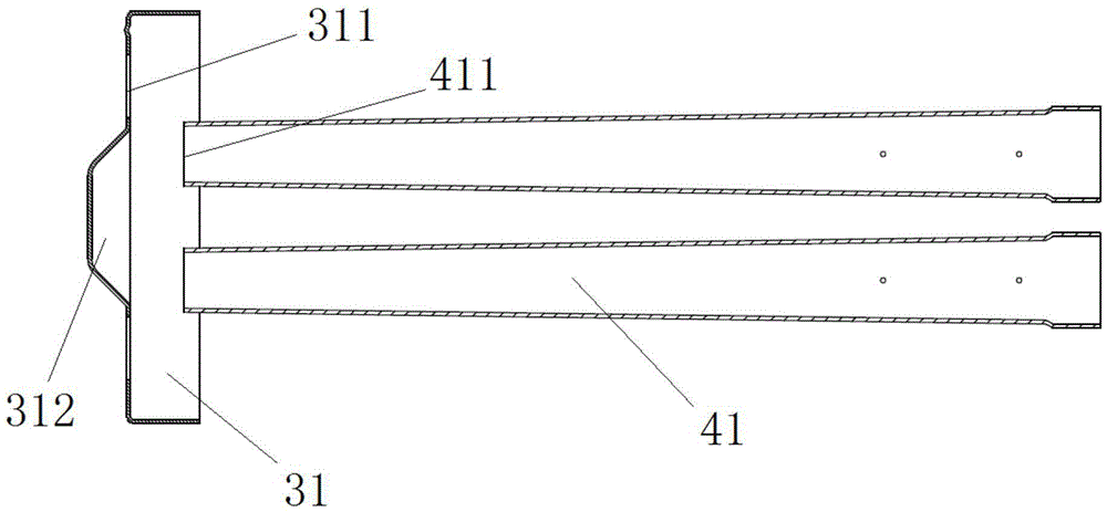
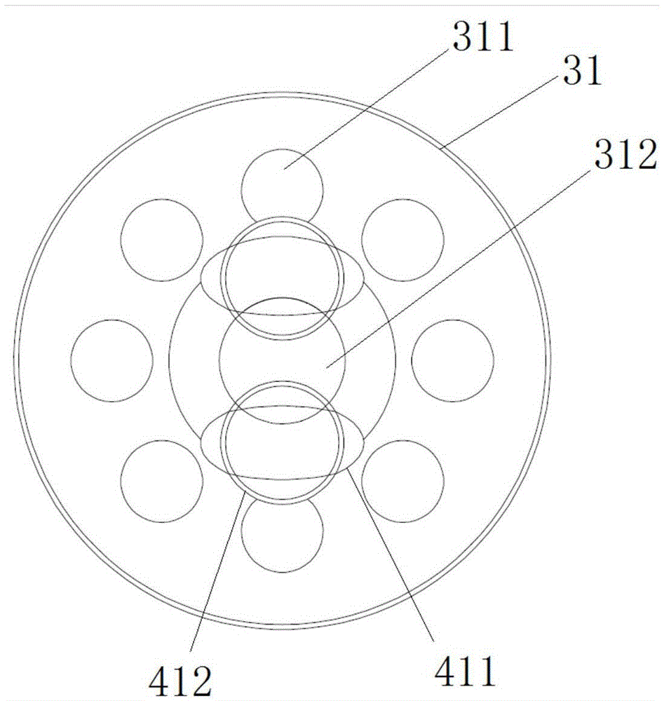
[0039] Preferably, this embodiment provides a liquid dispenser, compared with the previous embodiment, such as figure 2 and image 3 As shown, in this embodiment, a protrusion 312 is provided at the center of the filter screen support 31 . Wherein, a plurality of through holes 311 are evenly distributed around the protrusion 312 . Preferably, the filter screen support 31 in this embodiment is circular, and the distances from the plurality of through holes 311 to the center of the filter screen support 31 are equal.
[0040] Preferably, if figure 2 and image 3 As shown, in this embodiment, the air inlet 411 of the exhaust inner pipe 41 is set facing the area between the center of the filter screen support 31 and the through hole 311 . Here, in order that there is no facing area between the air inlet 411 of the exhaust inner pipe 41 and the through hole 311, the three schemes described in Embodiment 1 can also be adopted for the exhaust inner pipe 41 or the filter screen ...
Embodiment 3
[0043] Preferably, this embodiment provides a liquid dispenser, compared with Embodiment 2, such as Figure 2 to Figure 5 As shown, in this embodiment, the shape of the air inlet 411 of the exhaust inner pipe 41 is improved, and it is set as an ellipse. Such as image 3 As shown, there is no direct facing area between the air inlet 411 and the through hole 311 on the screen holder 31 after being arranged in an oval shape.
[0044] In the prior art, the air inlets of the exhaust pipes are all circular in shape. On the premise of ensuring that the area of the air inlets meets the conditions, the circular air inlets of the exhaust pipes of the liquid separators of the multiple exhaust pipes are all the same as the There is a facing area in the through hole on the filter screen support. Compared with the existing technology, such as figure 2 and image 3 As shown, the liquid separator provided in this embodiment avoids the existence of the air inlet 411 of the exhaust inner p...
PUM
 Abstract
Description
Claims
Application Information
 - R&D
- Intellectual Property
- Life Sciences
- Materials
- Tech Scout
- Unparalleled Data Quality
- Higher Quality Content
- 60% Fewer Hallucinations
Browse by: Latest US Patents, China's latest patents, Technical Efficacy Thesaurus, Application Domain, Technology Topic, Popular Technical Reports.
© 2025 PatSnap. All rights reserved.Legal|Privacy policy|Modern Slavery Act Transparency Statement|Sitemap|About US| Contact US: help@patsnap.com


