
Display panel and method for manufacturing same

A technology for display panels and manufacturing methods, applied in semiconductor/solid-state device manufacturing, electrical components, electric solid-state devices, etc., capable of solving problems affecting the color saturation of display panels, complex circuit design, and different brightness attenuation ranges of luminescent materials

Inactive Publication Date: 2016-04-27
HONG FU JIN PRECISION IND (SHENZHEN) CO LTD +1
View PDF3 Cites 12 Cited by
  • Summary
  • Abstract
  • Description
  • Claims
  • Application Information

AI Technical Summary

Problems solved by technology

However, the luminance of the organic luminescent materials of each primary color is different, and the luminance attenuation range of the luminescent materials of each primary color changes with the use time is also different, so that the color saturation of the display panel is affected.
In order to improve the color saturation of the display panel, it is necessary to use various circuit compensations to balance the brightness and color of the color display in the display, resulting in complex circuit design.

Method used


Image

  • Display panel and method for manufacturing same
  • Display panel and method for manufacturing same
  • Display panel and method for manufacturing same

Examples


Embodiment Construction

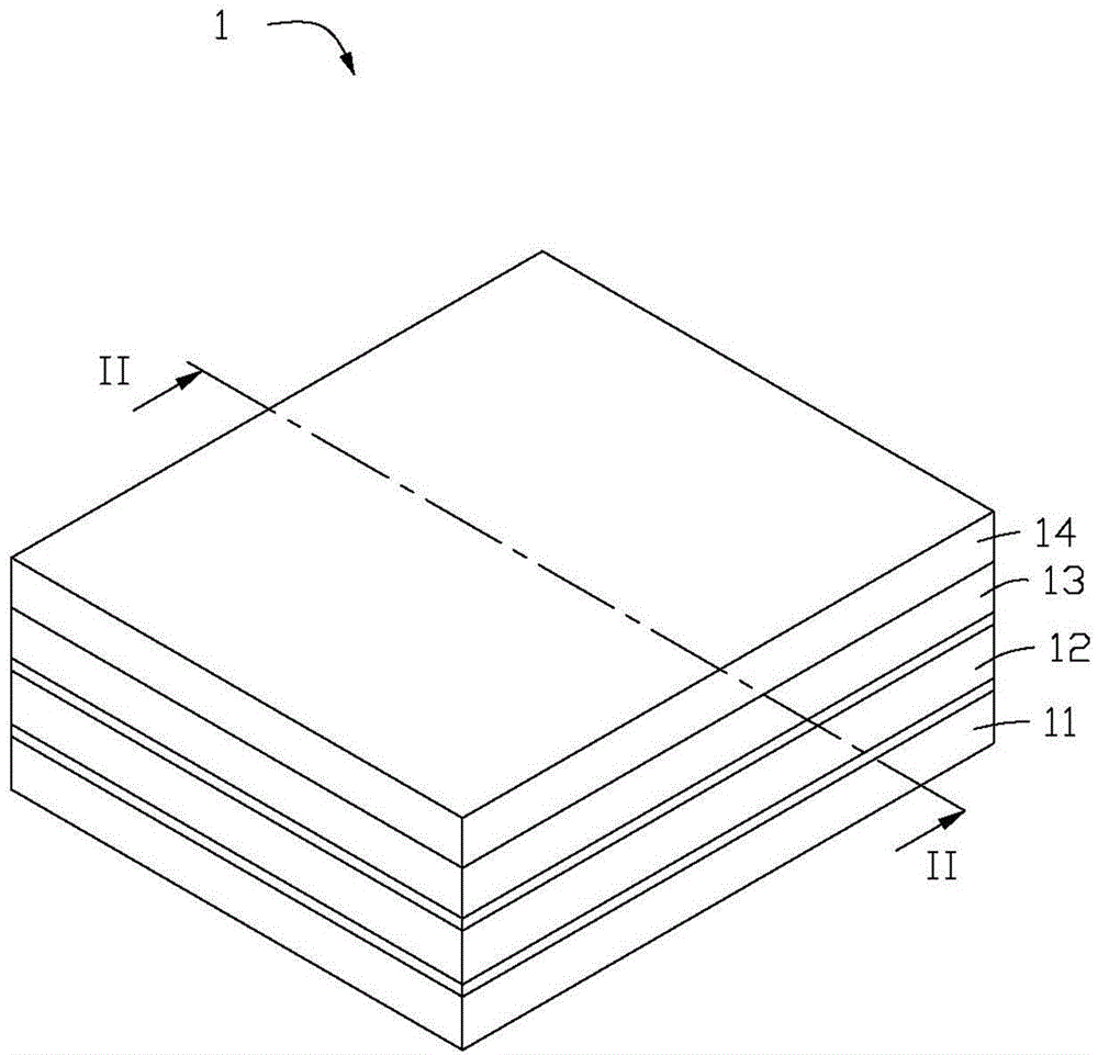
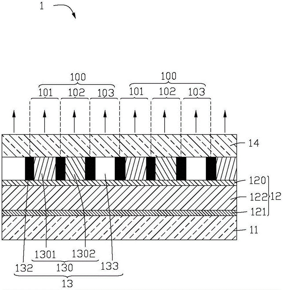
[0021] Such as figure 1 and figure 2 as shown, figure 1 is a schematic structural view of the display panel 1 provided in the first embodiment of the present invention, figure 2 yes figure 1 A cross-sectional view of panel 1 is shown in . In order to clearly illustrate the preferred embodiment of the present invention, the following figure 2 Only two pixels 100 of the display panel 1 are taken as an example for illustration. The display panel 1 includes a thin film transistor array 110 (see Figure 5 ) of the array substrate 11, the light emitting element 12 disposed on the array substrate 11, the color conversion layer 13 disposed on the light emitting side of the light emitting element 12, and the flat layer 14 covering the opposite side of the color conversion layer 13 and the light emitting element 12.

[0022] A plurality of pixels 100 are defined on the display panel 1 . Each pixel 100 includes at least a first sub-pixel 101 , a second sub-pixel 102 and a third...


PUM


Abstract

The invention provides a display panel, which comprises an array substrate, a light emitting element and a color conversion layer. One side surface of the array substrate is provided with a thin film transistor array. The light emitting element is arranged on one side of the array substrate on which the thin film transistor array is positioned. The color conversion layer is arranged on another side, opposite to the light emitting element, of the array substrate. The color conversion layer comprises a plurality of quantum dot blocks. The display panel defines a plurality of sub-pixels used for emitting light rays with different color components. The quantum dot blocks are arranged corresponding to the sub-pixels for converting light rays emitted by the light emitting element into full-color displayed light rays with three primary color components. The invention further provides a method for manufacturing the display panel.

Description

technical field [0001] The invention relates to a display panel and a method for manufacturing the display panel. Background technique [0002] The current organic electroluminescence display panel usually adopts the method of vapor-depositing organic light-emitting materials of three primary colors (sidebyside organic light emitting diode, Sidebyside OLED) arranged side by side on the substrate to realize full-color display. However, the luminance of the organic luminescent materials of each primary color is different, and the luminance attenuation range of the luminescent materials of each primary color changes with the use time is also different, so that the color saturation of the display panel is affected. In order to improve the color saturation of the display panel, it is necessary to use various compensation circuits in the display to balance the brightness and color of the color display, resulting in complex circuit design. Contents of the invention [0003] In v...

Claims


Application Information

Patent Timeline
Patent Type & Authority Applications(China)
IPC IPC(8): H01L27/32H01L21/77H01L27/12
Inventor 吴逸蔚郑荣安
Owner HONG FU JIN PRECISION IND (SHENZHEN) CO LTD
Learn More