A kind of rotor structure of built-in permanent magnet motor and motor with same

A rotor structure, permanent magnet motor technology, applied in the direction of magnetic circuit shape/style/structure, magnetic circuit rotating parts, magnetic circuit, etc., can solve the problems of reducing cogging torque and torque ripple, etc., to achieve reduction Cogging torque and torque ripple, efficiency does not decrease, and the effect of reducing cogging torque

Active Publication Date: 2018-09-25
GREE ELECTRIC APPLIANCES INC
View PDF7 Cites 2 Cited by
  • Summary
  • Abstract
  • Description
  • Claims
  • Application Information

AI Technical Summary

Problems solved by technology

[0006] Therefore, the technical problem to be solved by the present invention is to overcome the existence of permanent magnet motors in the prior art that can not only effectively reduce the cogging torque and torque ripple, but also maintain the original motor performance and work efficiency. defects, thereby providing a built-in permanent magnet motor rotor structure and a motor having the same

Method used


Image

  • A kind of rotor structure of built-in permanent magnet motor and motor with same
  • A kind of rotor structure of built-in permanent magnet motor and motor with same
  • A kind of rotor structure of built-in permanent magnet motor and motor with same

Examples


Embodiment Construction

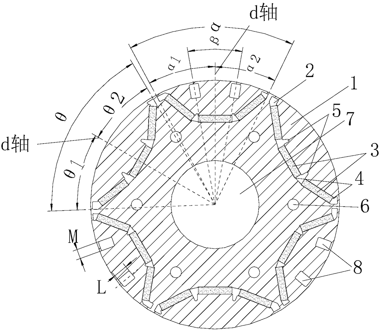
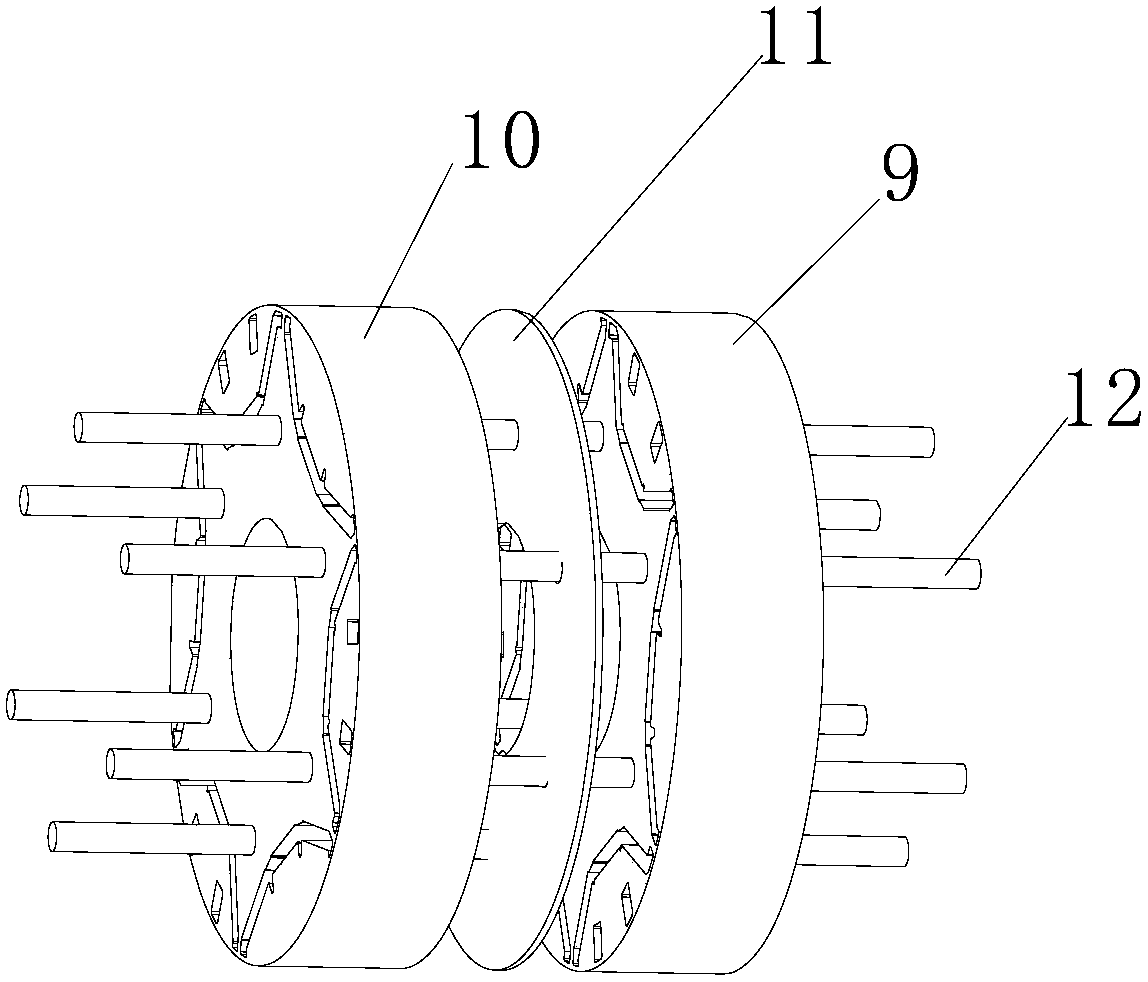
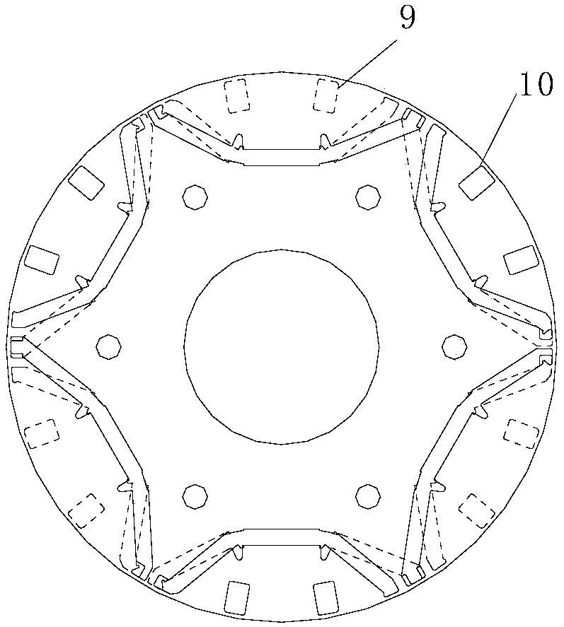
[0033] Such as Figure 1-3 As shown, the present invention provides a built-in permanent magnet motor rotor structure, including a rotor punch 1 (preferably a silicon steel sheet material) and a magnet 3 (preferably a magnetic steel) disposed inside the rotor punch 1 A plurality of magnetic slots 2, and shaft holes 7 pole rivet holes 6 matched with the rotating shaft, wherein the configuration of the N and S magnetic poles under a pair of rotor poles is different, defining the pole arc angle of the two magnetic poles under a pair of poles of the rotor structure They are the first pole arc angle α and the second pole arc angle θ respectively. The pole arc angle can be changed by setting asymmetric magnetic isolation holes near the end of the outer circular magnetic steel groove of the rotor. The first pole arc angle α is determined by the magnetic pole where it is located. The d-axis of the centerline is divided into α1 and α2 (α1 and α2 under the same pole satisfy: α1+α2=α), a...


PUM


Abstract

The invention provides a built-in permanent magnet motor rotor structure, which comprises a rotor plate (1) and a plurality of magnetic slots (2), wherein the plurality of magnetic slots (2) are arranged in the rotor plate (1) for placing magnetic bodies (3); two polar arc angles of magnetic poles under a pair of poles of the rotor structure are defined as a first polar arc angle alpha and a second polar arc angle theta; the first polar arc angle alpha is divided into alpha1 and alpha2 by a center line of the magnetic pole; the second polar arc angle alpha is divided into theta1 and theta2 by the center line of the magnetic pole; under the pair of poles, at least one pole meets the formula: theta1 is not equal to theta2 or alpha1 is not equal to alpha2; and one pair of poles is the poles formed by the magnetic bodies in two adjacent magnetic slots. Through the built-in permanent magnet motor rotor structure, applied moments of the magnetic poles and stator tooth sockets are partially offset; the tooth socket torques and torque ripples are effectively reduced; meanwhile, the running stability and reliability of an original motor can also be maintained or improved; and the efficiency of the motor is not reduced. The invention further relates to a motor with the rotor structure.

Description

technical field [0001] The invention belongs to the technical field of permanent magnet motors, and in particular relates to a built-in permanent magnet motor rotor structure and a motor having the same. Background technique [0002] In the prior art 1, the patent CN 1278472 C has V-shaped grooves and trimming grooves on the outer circle of the rotor, and the trimming grooves are asymmetrical. The phase of the torque and the torque generated by the winding is 180° to reduce the torque ripple. However, due to the different groove structure of the outer circle of each section of the iron core, the motor process is complicated, which is not convenient for mass production, and this may lead to a decline in the performance of the motor. Increased costs. [0003] 2. Authorized patents CN 102684337 B and CN 102624116 B provide a motor rotor segment structure, the angle between two adjacent rotor core poles is 360° / [N*LCM(Z1,2P)], N is the rotor segment Z1 is the number of stator ...

Claims


Application Information

Patent Timeline
Patent Type & Authority Patents(China)
IPC IPC(8): H02K1/27
CPCH02K1/276H02K2213/03
Inventor 史进飞陈彬肖勇吴曼
Owner GREE ELECTRIC APPLIANCES INC
Why Eureka
Try Eureka