
Dual power supply switching circuit and power supply equipment

A dual power supply switching and circuit technology, applied in the power supply field, can solve the problems of diode conduction voltage drop reducing power supply efficiency, etc., and achieve the effects of easy understanding, prevention of backfeeding, and elimination of large conduction voltage drop

Pending Publication Date: 2022-03-15
FU ZHOU INTERNET OF THINGS OPEN LAB
View PDF1 Cites 0 Cited by
  • Summary
  • Abstract
  • Description
  • Claims
  • Application Information

AI Technical Summary

Problems solved by technology

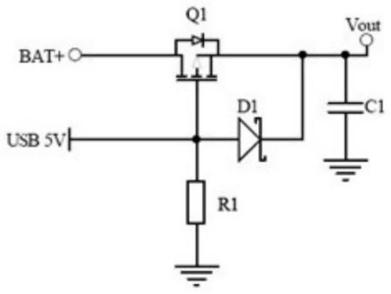
[0013] In view of the above problems, this application provides a dual power supply switching circuit and power supply equipment to solve the problem that in the existing power switching circuit, the USB 5V power supply branch needs to supply power to the load through a diode, and because the diode produces a large conduction voltage Reduced power usage efficiency issues

Method used


Image

  • Dual power supply switching circuit and power supply equipment
  • Dual power supply switching circuit and power supply equipment
  • Dual power supply switching circuit and power supply equipment

Examples


Embodiment Construction

[0052] In order to describe in detail the possible application scenarios, technical principles, specific solutions that can be implemented, goals and effects that can be achieved, etc., the following will be described in detail in conjunction with the listed specific embodiments and accompanying drawings. The embodiments described herein are only used to illustrate the technical solutions of the present application more clearly, so they are only examples, and cannot be used to limit the protection scope of the present application.

[0053] Reference herein to an "embodiment" means that a particular feature, structure, or characteristic described in connection with the embodiment can be included in at least one embodiment of the present application. The word "embodiment" appearing in various positions in the specification does not necessarily refer to the same embodiment, nor does it specifically limit its independence or relationship with other embodiments. In principle, in th...


PUM


Abstract

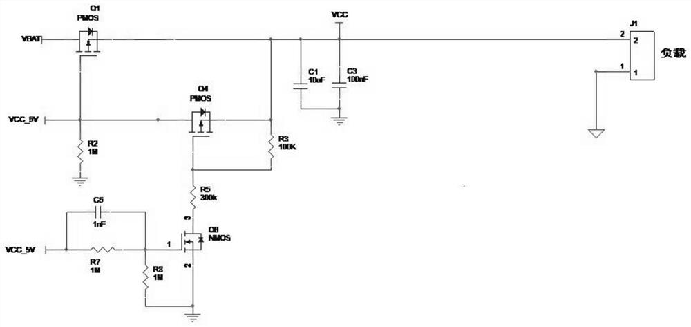
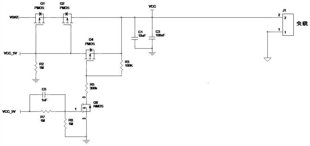
The invention relates to a dual-power switching circuit and power equipment. The dual-power switching circuit comprises a main power supply branch and an auxiliary power supply branch, the MOS tube Q4 is a P channel MOS tube, and the MOS tube Q6 is an N channel MOS tube; the drain electrode of the MOS tube Q4 is connected to a main power supply, the source electrode is connected to a load, and the grid electrode is connected to the drain electrode of the MOS tube Q6; a first body diode is arranged on the MOS tube Q4, the anode of the first body diode is connected to a main power supply, and the cathode of the first body diode is connected to a load; the grid electrode of the MOS tube Q6 is connected to a main power supply, and the source electrode is grounded; the auxiliary power supply branch comprises an MOS tube Q1, the MOS tube Q1 is a P-channel MOS tube, the grid electrode of the MOS tube Q1 is connected to the main power supply, the drain electrode of the MOS tube Q1 is connected to the auxiliary power supply, and the source electrode of the MOS tube Q1 is connected to a load. Seamless switching between the main power supply and the auxiliary power supply is achieved, the main power supply supplies power preferentially, the main power supply power supply branch and the auxiliary power supply power supply branch can effectively prevent reverse irrigation, and the power supply efficiency is hardly reduced.

Description

technical field [0001] This application relates to the field of power supplies, in particular to a dual power supply switching circuit and power supply equipment. Background technique [0002] At present, many electronic products have main power supply (via various power sources such as external adapter or USB) and auxiliary power supply (backup battery). Its power supply selection switching circuit has the following problems and shortcomings: [0003] 1) Mechanical switching takes time; [0004] 2) The power supply selection circuit often uses diode isolation to prevent the power supply and the battery from feeding each other, but the diode will produce a large voltage drop when it is conducting forward, which will undoubtedly reduce the power supply efficiency or battery life; [0005] 3) Backup power supply, that is, the battery voltage has a narrow range of adaptation, and is only suitable for single-cell lithium batteries (supply voltage is 3.6v ~ 4.2v); [0006] 4) ...

Claims


Application Information

Patent Timeline
IPC IPC(8): H02J9/06H02J7/36H02H3/08
CPCH02J9/06H02J7/36H02H3/08
Inventor 张亮王博涂振益吴圣鑫许志伟欧志宝周涛涛
Owner FU ZHOU INTERNET OF THINGS OPEN LAB
Learn More