
Miniature coreless generator

An ironless, generator technology, applied in electrical components, electromechanical devices, electric components, etc., can solve the problems of coil winding copper loss, reduce motor efficiency, increase driving power, etc., to increase product service life and improve product quality. Work efficiency, the effect of increasing the torque to volume ratio

Inactive Publication Date: 2016-04-27
珠海市三森电子科技有限公司
View PDF6 Cites 2 Cited by
  • Summary
  • Abstract
  • Description
  • Claims
  • Application Information

AI Technical Summary

Problems solved by technology

This method has the following disadvantages: 1. Using the iron core stator structure, there is a certain iron loss and magnetic damping. When the driving power is increased, the iron loss and copper loss will increase and the motor efficiency will be reduced; 2. There is copper loss in the coil winding; 3. The traditional radial magnetic field structure design, the power density and torque volume are relatively small, and the magnetic circuit loss is large
At present, a large number of electronic information products have put forward higher and higher technical requirements for self-generation and self-storage technologies. However, due to the limitations of traditional technical solutions and process design, traditional self-generation (that is, iron-core generators) has Unable to meet market demand, so there is an urgent need for a new generation of self-generation technology to meet market demand

Method used


Image

  • Miniature coreless generator
  • Miniature coreless generator
  • Miniature coreless generator

Examples


Embodiment Construction

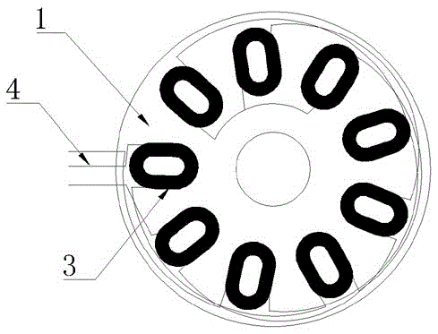
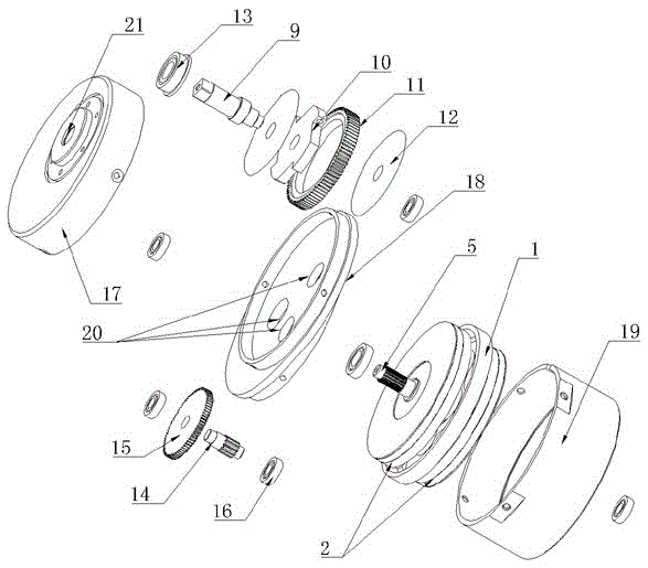
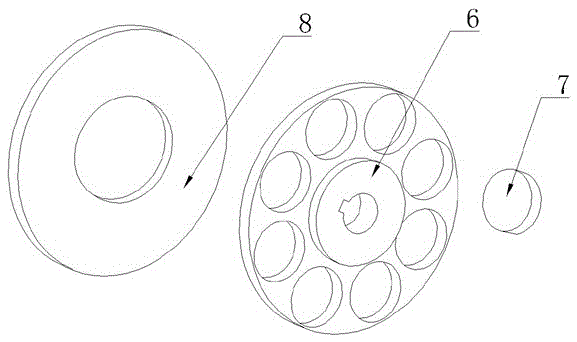
[0015] Such as figure 1 , figure 2 and image 3 As shown, the present invention includes a casing and a transmission part arranged in the casing, and a power generation part connected with the transmission part is also arranged in the casing, and the power generation part includes a coil skeleton (1) and the magnet rotor (2) attached to the left and right ends of the coil bobbin (1), the coil bobbin (1) is fixedly arranged on the casing, and evenly distributed on any side of the coil bobbin (1) There are several coils (3), and every two adjacent coils (3) are electrically connected, and three output lines electrically connected to the coils (3) are also arranged on the coil frame (1) (4), a motor shaft (5) connected to the transmission part is further arranged on the coil frame (1), and the magnet rotor (2) is fixedly connected to the motor shaft (5). In the present invention, the magnet rotor (2) includes an iron positioning ring (6), magnets (7) evenly distributed on the...


PUM


Abstract

The invention discloses and provides a miniature coreless generator, which can effectively improve the work efficiency of a product and prolong the service lifetime of the product. The miniature coreless generator comprises a casing and a transmission part, wherein the transmission part is arranged in the casing; a power generation part connected with the transmission part is also arranged in the casing; the power generation part comprises a coil framework (1) and magnet rotors (2); the magnet rotors (2) are attached to the left end and the right end of the coil framework (1); the coil framework (1) is fixedly arranged on the casing; a plurality of coils (3) are evenly distributed on any surface of the coil framework (1); every two adjacent coils (3) are electrically connected with each other; a three-phase output line (4) which is electrically connected with the coils (3) is also arranged on the coil framework (1); a motor shaft (5) which is connected with the transmission part is also arranged on the coil framework (1); and the magnet rotors (2) are fixedly connected with the motor shaft (5).

Description

technical field [0001] The invention relates to a power generation device, in particular to a miniature coreless generator applied in the field of high-precision self-power generation. Background technique [0002] Most of the micro-generator technologies used in the industry at this stage still use traditional silicon steel sheets and wound stator structures as core materials, and generate electrical energy output through the transmission structure of motors and gears. This method has the following disadvantages: 1. Using the iron core stator structure, there is a certain iron loss and magnetic damping. When the driving power is increased, the iron loss and copper loss will increase and the motor efficiency will be reduced; 2. There is copper loss in the coil winding; 3. With the traditional radial magnetic field structure design, the power density and torque volume are relatively small, and the magnetic circuit loss is relatively large. At present, a large number of elect...

Claims


Application Information

Patent Timeline
Patent Type & Authority Applications(China)
IPC IPC(8): H02K7/18H02K3/46H02K5/04
CPCH02K7/1807H02K1/2753H02K3/46H02K5/04
Inventor 郭晓林
Owner 珠海市三森电子科技有限公司
Learn More