
Roll cutting method and associated equipment

A hobbing and equipment technology, which is used in the field of rotation driven by the rotation axis of the piece, can solve the problems of reducing the processing quality, shortening the tool life, vibration, etc., and achieves the effect of increasing the number of processes and increasing the cutting speed.

Active Publication Date: 2019-06-11
PROFILATOR
View PDF10 Cites 0 Cited by
  • Summary
  • Abstract
  • Description
  • Claims
  • Application Information

AI Technical Summary

Problems solved by technology

At large depths of cut, i.e. when cutting or running teeth with a large tooth module, this leads to vibrations and consequently reduced machining quality and tool life

Method used


Image

  • Roll cutting method and associated equipment
  • Roll cutting method and associated equipment
  • Roll cutting method and associated equipment

Examples


Embodiment Construction

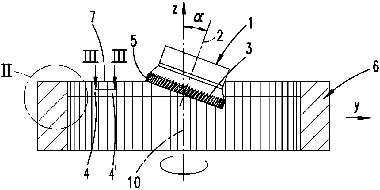
[0025] With the equipment described below, the internal teeth or external teeth are cut in the blank by the hobbing method. This is done by cutting the gear 1 either on the inner or outer surface of the smooth wall of the blank, or in the tooth flanks of the blank with prefabricated teeth. This method consists of a number of successive roughing processes, in which the roughing is performed once. After many rough machining processes, at least one finishing process can be connected, and then a finishing process is performed. The difference between finishing and rough cutting is mainly to reduce the transverse feed, that is, a smaller cutting amount, but still through a changed feed rate.

[0026] in Image 6 The equipment shown in has a frame not shown in the figure, which carries a tool spindle 11 with a chuck, and a cutting gear 1 with cutting teeth 3 is fixed in the chuck. The tool spindle 11 can be driven to rotate by an electric drive 12. The driver 12 is controlled by the ...


PUM


Abstract

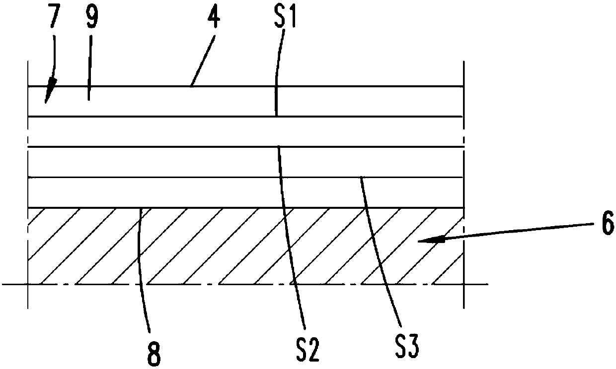
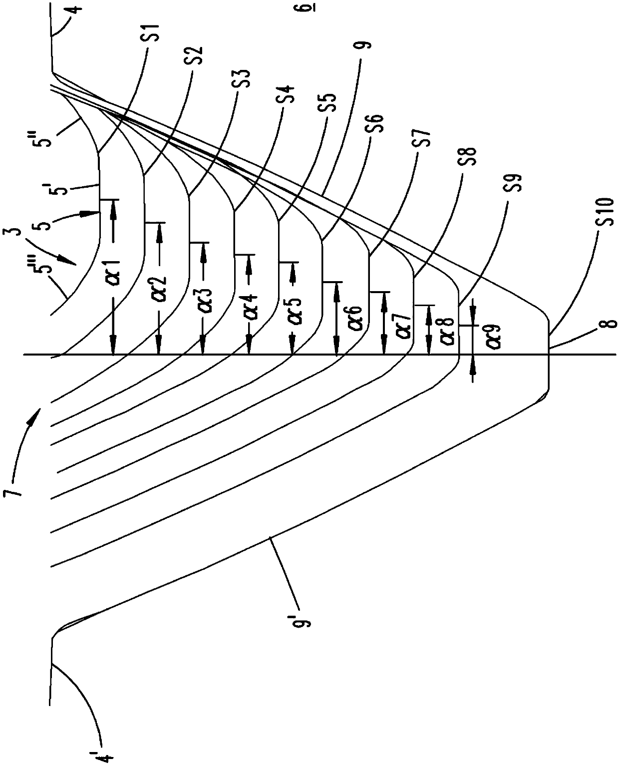
The invention relates to a method and a device for gearing a wheel blank (6) by hobbing with a cutting gear (1) having cutting teeth (3), comprising a workpiece spindle and a tool spindle for mounting the wheel blank (6) , wherein the tool spindle and the workpiece spindle are positioned relative to each other according to the angle (α) between the axes, wherein the gearing is carried out in a plurality of successive processes (S1 to S20), wherein, by feeding a , progressively deepens the backlash (7) between the teeth to be produced, wherein the axial distance between the tool spindle and the workpiece spindle, and a tooth, for example between the first and second flanks (9, 9'), A fixed point at the center of the gap (7), relative to a fixed point on the cutter (3), such as the rotation angle (α1 to α19) of the center of the cutter (3), is changed between operations such that the cutter ( 3) of the first edge section (5"), with at least a reduced amount of cutting compared with the other edge sections (5', 5"') of the cutting tooth (3), to the first tooth flank (9 ) of a flank segment of a second flank (9') that has been produced in a previous process.

Description

Technical field [0001] The present invention relates to a method for hobbing by using a cutting gear with cutting teeth The method for making teeth for a wheel blank includes a workpiece spindle that is driven to rotate around the workpiece rotation axis for mounting the wheel blank, and a tool spindle with a cutting gear that is driven to rotate around the tool rotation axis, wherein the tool spindle and the workpiece The spindles are mutually positioned according to the axis included angle, and the drive of the tool spindle and the workpiece spindle is driven to rotate at a specified speed ratio. Among them, the gear making is carried out in multiple successive processes, and there is at least one axial component along the workpiece spindle. While changing the distance between the tool spindle and the workpiece spindle axis, the gap between the teeth to be machined is gradually deepened. [0002] In addition, the present invention also relates to a device for implementing the m...

Claims


Application Information

Patent Timeline
Patent Type & Authority Patents(China)
IPC IPC(8): B23F5/16
CPCB23F5/163Y10T409/101749Y10T409/105565G05B19/186
Inventor E.普罗克M.索布齐克
Owner PROFILATOR
Learn More