A combination chair connector

A technology for connecting parts and combining chairs, which is applied to chairs, reclining chairs, folding chairs, etc., can solve the problems of easy loosening of screws, easy fatigue during sitting time, and inconvenient adjustment, and achieves convenient production, low cost and simple structure. Effect

Active Publication Date: 2019-01-18
ANJI HAILONG FURNITURE
View PDF12 Cites 0 Cited by
  • Summary
  • Abstract
  • Description
  • Claims
  • Application Information

AI Technical Summary

Problems solved by technology

[0002] Chairs are very common and frequently used furniture in daily life. There are many kinds of shapes and structures. For the convenience of transportation, most chairs are detachable now. It is easy to loosen, and the angle between the seat back and the seat seat is fixed after installation, which is inconvenient for users to adjust later, and it is easy to get tired after sitting for a long time. At present, there are also connecting parts connecting the seat back and seat seat invented, such as the announcement No. CN203641202U (2014-06-11) discloses a separate chair connector, which is composed of a tenon part and a mortise part, wherein rectangular guide strips protrude from both sides of the front of the tenon part, and extend out from the bottom of the tenon part. An elastic protruding end, protruding from the protruding end has an undercut, the backrest connection hole is provided on the tenon part, the back of the tenon part is the backrest connection surface, and the seat connection hole is provided on the mortise part. There are rectangular grooves on both sides of the back of the part, and the rectangular grooves are matched with the rectangular guide strips. The lower end of the mortise part is provided with an undercut baffle and a tenon baffle, and the front of the mortise part is the seat connection surface.
Although this invention facilitates the installation and disassembly of the backrest and provides mechanical support for the backrest, the connecting piece cannot satisfy the angle adjustment between the backrest and the seat, and cannot provide users with a more comfortable use environment

Method used


Image

  • A combination chair connector
  • A combination chair connector
  • A combination chair connector

Examples


Embodiment Construction

[0025] The present invention will be described in further detail below in conjunction with the accompanying drawings.

[0026] This specific embodiment is only an explanation of the present invention, and it is not a limitation of the present invention. Those skilled in the art can make modifications to this embodiment without creative contribution as required after reading this specification, but as long as they are within the rights of the present invention All claims are protected by patent law.

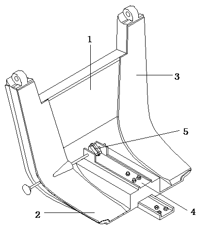
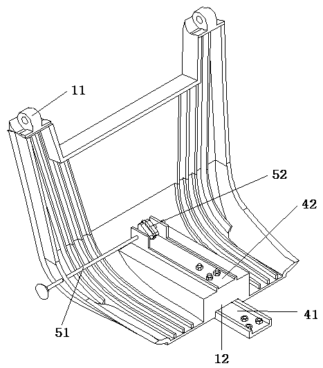
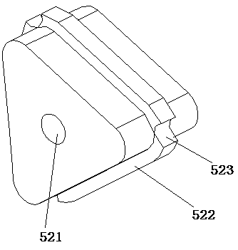
[0027] Such as figure 1 , figure 2 , image 3 with Figure 4 As shown, a combined chair connector, which includes a connecting body 1, is arranged on the connecting body 1 for connecting and fixing the fixing part 4 of the connecting body 1 and the seat, and is arranged on the connecting body 1 and connected with the fixing part 4 and used The limit part 5 for adjusting the inclination of the chair back;

[0028] The connecting body 1 includes a first connecting portion 11 f...


PUM


Abstract

The invention discloses a combined chair connector which comprises a connecting body, a fixing part and a limiting part, wherein the fixing part is arranged on the connecting body and is used for connecting and fixing the connecting body and a seat; the limiting part is arranged on the connecting body and connected with the fixing part and is used for adjusting the slope of a chair back; the connecting body comprises a first connecting part which is used for connecting the connecting body and the chair back; the limiting part comprises a limiting rod and a limiting block; the limiting rod is arranged on the connecting body; the limiting block is arranged on the limiting rod; a hole for fixing the limiting rod in a penetrating manner is formed in the width direction of the limiting block; limiting strips are arranged at the side surface of the limiting block; and limiting holes are formed between the adjacent limiting strips. The combined chair connector is simple in structure, low in fabrication cost, safe and comfortable to use, and suitable for wide-scope popularization and application.

Description

technical field [0001] The invention relates to a connecting piece, in particular to a connecting piece for a combined chair. Background technique [0002] Chairs are very common and frequently used furniture in daily life. There are many kinds of shapes and structures. For the convenience of transportation, most chairs are detachable now. It is easy to loosen, and the angle between the seat back and the seat seat is fixed after installation, which is inconvenient for users to adjust later, and it is easy to get tired after sitting for a long time. At present, there are also connecting parts connecting the seat back and seat seat invented, such as the announcement No. CN203641202U (2014-06-11) discloses a separate chair connector, which is composed of a tenon part and a mortise part, wherein rectangular guide strips protrude from both sides of the front of the tenon part, and extend out from the bottom of the tenon part. An elastic protruding end, protruding from the protru...

Claims


Application Information

Patent Timeline
Patent Type & Authority Patents(China)
IPC IPC(8): A47C4/02A47C1/024A47C7/00
CPCA47C1/024A47C4/02A47C4/021A47C7/00
Inventor 沈海龙
Owner ANJI HAILONG FURNITURE
Why Eureka
Try Eureka