Reversed punching structure aiming at inclined plane shapes and punching process

A technology of reverse punching and hole structure, which is applied in the field of stamping processing molds, can solve the problems of damage to the die, poor precision, and increase the repair rate of the mold, so as to avoid movement, improve processing accuracy and processing quality.

Inactive Publication Date: 2016-05-04
FOSHAN CHENGYANG ZHENGDA MOLD HARDWARE PLASTIC CO LTD
View PDF5 Cites 2 Cited by
  • Summary
  • Abstract
  • Description
  • Claims
  • Application Information

AI Technical Summary

Problems solved by technology

[0004] The purpose of the present invention is to provide a reverse punching structure and punching process for the shape of the inclined plane, so as to solve the problem that the oblique wedge structure arranged on the pressing core in the prior art will affect the oblique wedge due to the slight inclination of the pressing core. The deviation of the punch position causes poor precision or damages the die, which affects the production of the machine and increases the mold repair rate.

Method used


Image

  • Reversed punching structure aiming at inclined plane shapes and punching process
  • Reversed punching structure aiming at inclined plane shapes and punching process
  • Reversed punching structure aiming at inclined plane shapes and punching process

Examples


Embodiment Construction

[0029] In order to make the object, technical solution and advantages of the present invention more clear and definite, the present invention will be further described in detail below with reference to the accompanying drawings and examples.

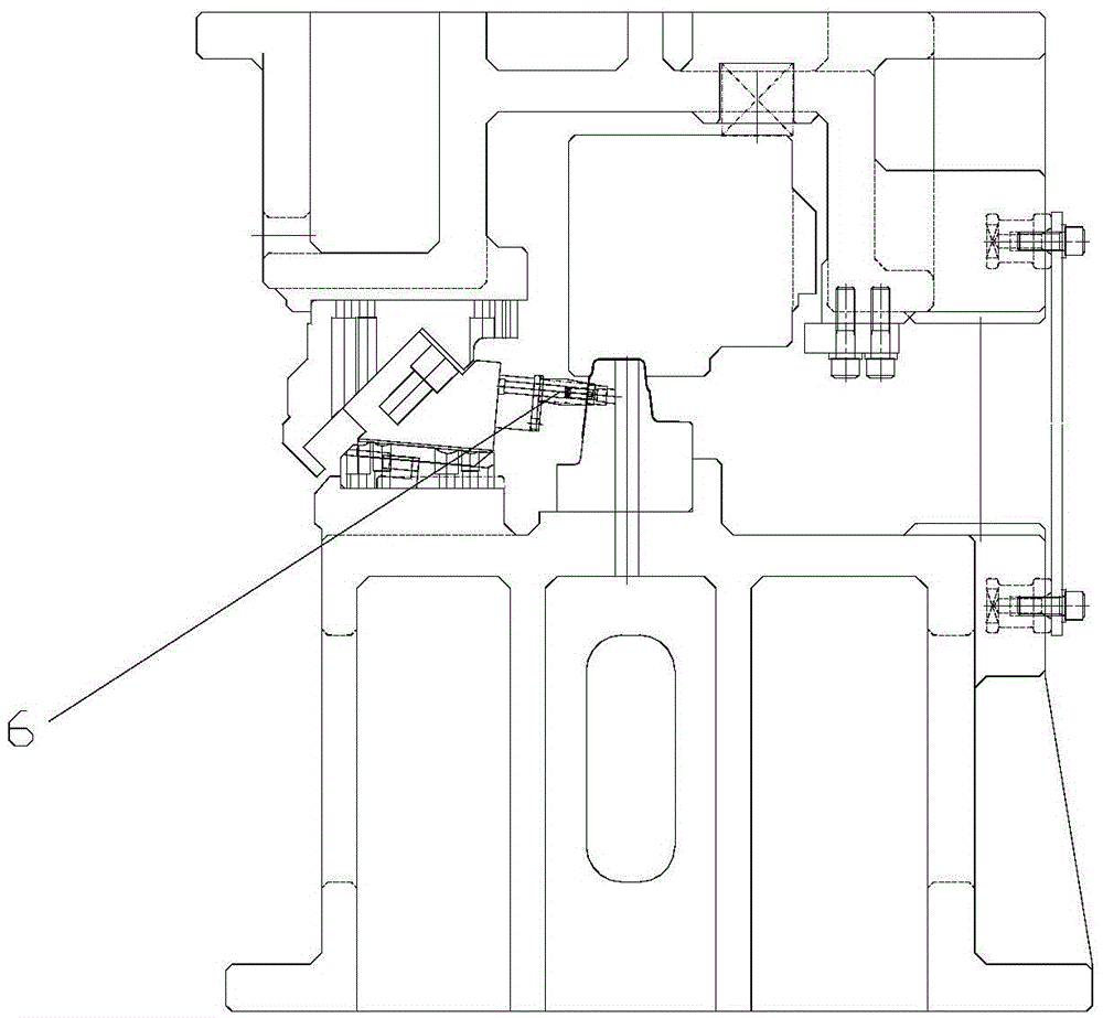
[0030] refer to figure 1 , figure 1 It is a schematic diagram of the punch setting structure of the stamping die in the prior art. The punch 6 punches the workpiece from left to right, and the driving block driving the punch 6 is likely to interfere with the workpiece to be processed; in addition, the punch of this type of structure When the workpiece is directly punched, the reaction force caused by the force applied to the workpiece during processing is applied to the punch 6, which easily causes the punch to move and travel unstable, and reduces the processing accuracy.

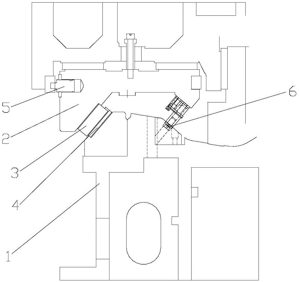
[0031] refer to figure 2 , the present invention provides a reverse punching structure aimed at the shape of the inclined plane, which includes a base 1 and a sli...


PUM


Abstract

The invention discloses a reversed punching structure aiming at inclined plane shapes. The reversed punching structure comprises a base, a sliding block, and a puncher pin, wherein a first driving block is arranged at one end of the lower part of the sliding block, a second driving block is arranged at the upper part of the base, the first driving block is connected in a sliding manner with the second driving block, the puncher pin is used for punching a workpiece to be processed, and the puncher pin is arranged at one end of the lower part of the sliding block. Due to the adoption of the reversed punching structure provided by the invention, the problem of not high processing accuracy caused by displacement of the puncher pin in the prior art can be effectively solved, in addition, the problem that the driving block of a die driving puncher pin in the prior art can probably cause interference with workpieces of products can be solved.

Description

technical field [0001] The invention relates to the field of stamping dies, in particular to a reverse punching structure and punching process for inclined plane shapes. Background technique [0002] Existing stamping dies generally use angles of rotation or wedges to process inclined holes, but for multi-station automatic stamping dies, the angles of rotation will cause clamping problems of the manipulator and unstable feeding. Obviously, the angle of rotation is unrealistic. , so most of the multi-station automatic stamping dies use wedges to process the holes on the inclined surface of the parts. The conventional practice is to set the drive block of the wedges in the space outside the parts, but for large parts (or the same position in the mold space) Not allowed) The hole to be processed is on the slope in the middle of the part and is at a reverse angle (inward). In this case, the entire wedge mechanism is generally placed on the pressing core, but this structure will ...

Claims


Application Information

Patent Timeline
Patent Type & Authority Applications(China)
IPC IPC(8): B21D28/34
CPCB21D28/34
Inventor 周冠华
Owner FOSHAN CHENGYANG ZHENGDA MOLD HARDWARE PLASTIC CO LTD
Why Eureka
Try Eureka