Dual-layer vibration-damping fastener for city railway
What is Al technical title?
Al technical title is built by PatSnap Al team. It summarizes the technical point description of the patent document.
A vibration-damping fastener and railway technology, applied in roads, tracks, buildings, etc., can solve the problems of difficulty in repairing and replacing the vibration-damping cushion, easy peeling of the vulcanized rubber layer, high maintenance and repair costs, etc., and achieves easy maintenance and vibration reduction effects Good, easy to promote the effect of use
Active Publication Date: 2016-05-04
ANHUI CHAOHU CASTING FACTORY +1
View PDF9 Cites 14 Cited by
Summary
Abstract
Description
Claims
Application Information
AI Technical Summary
This helps you quickly interpret patents by identifying the three key elements:
Problems solved by technology
Method used
Benefits of technology
Problems solved by technology
The main disadvantage of the overall vulcanized shear type damping fastener is that the stiffness cannot be adjusted, and the vulcanized rubber layer is easy to peel off. Once the vulcanized rubber layer is damaged, the entire fastener needs to be replaced, and the maintenance cost is high.
The main disadvantage of the double-layer compression damping fastener is that it adopts a double-layer iron backing structure, which is expensive to use, and an independent locking structure is required between the two iron backing plates, which is not easy to disassemble, and it is difficult to maintain and replace the vibration-damping backing.
Method used
Image
Click on the blue label to locate the original text in one second.
Reading with bidirectional positioning of images and text.
Examples
Embodiment Construction
[0020] The present invention will be described in further detail below according to the drawings and embodiments.
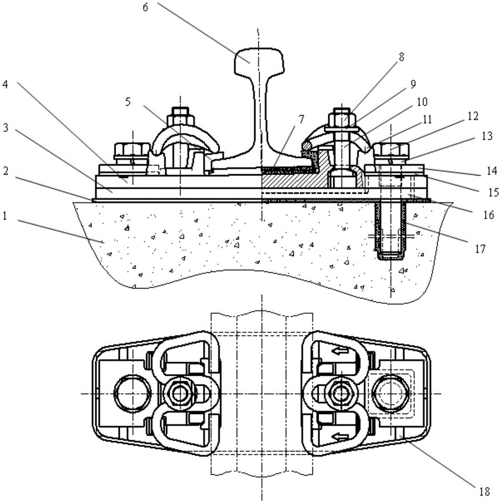
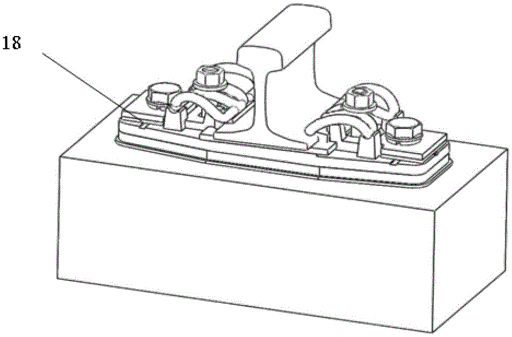
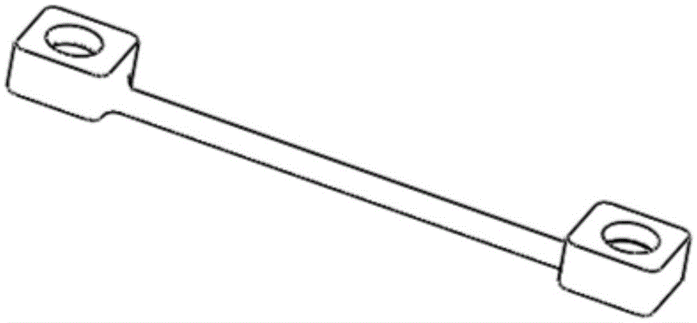
[0021] refer to Figure 1-Figure 2 In the present invention, a nylon sleeve 17 is pre-embedded in the base 1, the insulating cushion plate 2 is directly laid on the base 1, and the iron connecting rod 16, the elastic cushion layer 3 and the upper layer are sequentially laid on the insulating cushion plate 2 The iron backing plate 4, the insulating gland 15 and the pressure plate 14 are installed on the iron connecting rod 16, the height is slightly lower than the sum of the height of the elastic backing layer 3 and the upper iron backing plate 4, when the anchor bolt 12 passes through the heavy spring washer 13 downward 1. The bolt holes on the pressing plate 14 and the insulating gland 15 run through the iron connecting rod 16, and when screwed into the nylon sleeve 17 fixed on the base 1, the height space formed by the iron connecting rod 16 column 19 and the n...
PUM
Abstract
The invention discloses a dual-layer vibration-damping fastener for a city railway. The dual-layer vibration-damping fastener comprises a base, an insulation buffer cushion plate, an elastic cushion layer, an upper-layer iron cushion plate, an insulation gauge block, a steel rail, an under-rail rubber cushion plate, a nut, a flat washer, T-shaped bolts, an elastic strip, anchor bolts, heavy spring washers, pressing plates, an insulation press cover, an iron connecting rod, and a nylon sleeve pipe. The dual-layer vibration-damping fastener disclosed by the invention has the beneficial effects that a creative designed structure without a lower-layer iron cushion plate is adopted, a special tool is not needed, and the dual-layer vibration-damping fastener can be manually disassembled; the elastic cushion layer is simple to repair and replace, and the conservation and the repair are facilitated; the iron connecting rod is used, so that the two anchor bolts are stressed at the same time, the operating state of the anchor bolts is optimized, the safety of the fasteners is improved, besides, the structure is simple, and the cost is low.
Description
technical field [0001] The invention relates to a double-layer vibration-damping fastener, in particular to a double-layer vibration-damping fastener for urban railways. Background technique [0002] Urban railways refer to railways connecting two cities, generally in a certain area, such as the Pearl River Delta, the Yangtze River Delta, and the Bohai Rim. The overall requirements of the line are between the subway and the high-speed railway, and the maximum operating speed is required to be 120km / h~140km / h. The high-speed rail EMU trains are used, and the high-speed railway standard design is used. In the section of the line that requires vibration reduction, it is required to lay fasteners with vibration and noise reduction effects. The vibration and noise reduction effect of the fasteners is required to be 3-5dB compared with the section of high-speed railway fasteners. The application of vibration and noise reduction fasteners under such high speed and large axle load ...
Claims
Application Information
Patent Timeline
Application Date:The date an application was filed.
Publication Date:The date a patent or application was officially published.
First Publication Date:The earliest publication date of a patent with the same application number.
Issue Date:Publication date of the patent grant document.
PCT Entry Date:The Entry date of PCT National Phase.
Estimated Expiry Date:The statutory expiry date of a patent right according to the Patent Law, and it is the longest term of protection that the patent right can achieve without the termination of the patent right due to other reasons(Term extension factor has been taken into account ).
Invalid Date:Actual expiry date is based on effective date or publication date of legal transaction data of invalid patent.