
Overweight combined highway and railway bridge rigid suspending cable stiffened continuous steel trussed beam pushing device with stiffening string

A technology of road-rail dual-purpose bridge and jacking device, which is applied in the field of bridge steel structure, can solve problems such as inability to meet the jacking requirements, and achieve the effect of ensuring stability and safety and ensuring construction safety

Inactive Publication Date: 2016-05-04
STEEL STRUCTURE CONSTR CO LTD OF CHINA TIESUU CIVIL ENG GRP
View PDF5 Cites 5 Cited by
  • Summary
  • Abstract
  • Description
  • Claims
  • Application Information

AI Technical Summary

Problems solved by technology

Rigidly stiffened chord jacking requires strict control of bridge alignment and multi-point synchronous jacking. Existing jacking devices cannot meet the requirements of rigid suspension cable-stiffened continuous steel truss girder with stiffened chord jacking for super-heavy highway and railway bridges.

Method used


Image

  • Overweight combined highway and railway bridge rigid suspending cable stiffened continuous steel trussed beam pushing device with stiffening string
  • Overweight combined highway and railway bridge rigid suspending cable stiffened continuous steel trussed beam pushing device with stiffening string
  • Overweight combined highway and railway bridge rigid suspending cable stiffened continuous steel trussed beam pushing device with stiffening string

Examples


Embodiment Construction

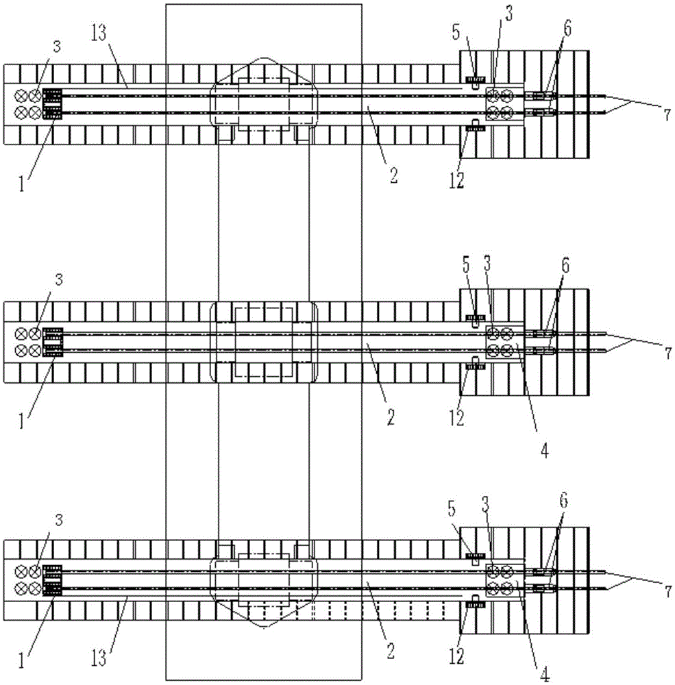
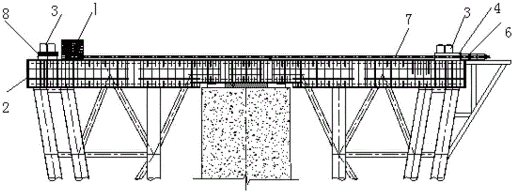
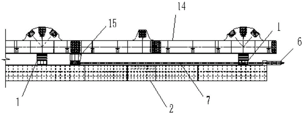
[0019] Referring to the accompanying drawings, a rigid suspension cable-stiffened continuous steel truss beam with stiffened chord thrusting device for a super-heavy road-rail dual-purpose bridge includes a sliding device, a vertical jacking device, a horizontal jacking system device, and a lateral deviation correction device. In that: the sliding device includes left, middle and right three-truss sliders 1 and a slideway beam 2, the left, middle and right three-truss sliders 1 are respectively located above the slideway beam 2, and the left, middle and right three The bottom of the truss slider 1 is respectively equipped with an MGE material slide plate 10 for oil passage, and the top of the slideway beam 2 is laid with a full-length MGE material stainless steel plate 12; Jacking jack 3, horizontal reaction force seat 4, distribution beam 8, said horizontal reaction force seat 4 is fixed on the front end of slideway beam 2, said distribution beam 8 is respectively placed on th...


PUM


Abstract

The invention discloses an overweight combined highway and railway bridge rigid suspending cable stiffened continuous steel trussed beam pushing device with a stiffening string. The pushing device comprises a sliding device, a vertical jacking device, a horizontal pushing system device and a transverse deviation rectifying device. The sliding device comprises a left girder sliding block, a middle girder sliding block and a right girder sliding block and slideway beams. The sliding blocks are located above the slideway beams, MGE sliding plates with oil channels are arranged at the bottoms of the sliding blocks, and a long MGE stainless steel plate is laid on the tops of the slideway beams. The vertical jacking device comprises a left girder vertical lifting jack, a middle girder vertical lifting jack, a right girder vertical lifting jack, a horizontal counter force seat and distributive girders, and the horizontal contour force seat is fixed to the front ends of the slideway beams. The transverse deviation rectifying device comprises limiting check blocks, deviation rectifying jacks and lateral counter force seats, limiting check blocks are arranged on the left side of the left girder slidway beam and the right side of the right girder slidway beam, no check block is arranged on the middle girder slideway beam, the lateral counter force seats are located on the outer side of the front end of the left girder slideway beam, the outer side of the front end of the middle girder slideway beam and the outer side of the front end of the right girder slideway beam, pistons at the front ends of the deviation rectifying jacks press the outer side walls of the sliding blocks, and the rear ends of the deviation rectifying jacks are limited through the lateral counter force seats.

Description

technical field [0001] The invention relates to the technical field of bridge steel structures, in particular to a rigid suspension cable-stiffened continuous steel truss girder with stiffened chord jacking device for super-heavy road-rail dual-purpose bridges, which is mainly used for jacking erection of steel truss girders with stiffened chords. Background technique [0002] Rigid suspension cable-stiffened steel truss bridge is a novel long-span road-rail bridge structure. At present, there is only one bridge of this structure in China. This rigid suspension cable-stiffened steel truss bridge crosses the main trough of the Yellow River, with a span of (123+3*180+128) m and a total bridge weight of 37,000t. It is installed and erected by the jacking method. Due to the large span of the steel truss girder, the slender stiffening chord of the rigid suspension cable, and the excessive tonnage of the bridge, the structural system of the stiffening chord will be unstable due to...

Claims


Application Information

Patent Timeline
Patent Type & Authority Applications(China)
IPC IPC(8): E01D21/00
CPCE01D21/00
Inventor 李荣浩伍军梁崇双张时利刘瑜曹晗丁仕洪邢文彬伍超然阮蔚平易中楼夏云李富张士宝
Owner STEEL STRUCTURE CONSTR CO LTD OF CHINA TIESUU CIVIL ENG GRP
Learn More