
Rolling wheel trolley device integrating traveling function with limiting adjusting function

An adjustment device and position-limiting technology, which is applied in the erection/assembly of bridges, the processing of building materials, bridges, etc., can solve the problem of high cost of walking automatic pushing equipment, heavy steel structure flat slideway structure, increased manpower and material resources, etc. cost and other issues, to achieve the effect of saving labor costs, shortening the construction period, and improving the construction safety factor

Active Publication Date: 2016-05-04
中铁十局集团有限公司
View PDF6 Cites 5 Cited by
  • Summary
  • Abstract
  • Description
  • Claims
  • Application Information

AI Technical Summary

Problems solved by technology

In the above-mentioned construction, the walking-type automatic jacking equipment is expensive, the construction speed is slow, and the construction period is long; the steel structure flat slideway has a heavy structure, high friction resistance, and the construction speed is slow; the roller trolley slideway has small structures and heavy weight. Lightweight, low frictional resistance, fast construction speed, short cycle, etc. However, in the push / drag construction, the direction deviation is easy to occur due to the high speed, and when the deviation is large, it is necessary to stop the construction to adjust and correct the deviation, and correct the deviation in the static state Prolonged construction time and increased costs such as manpower and material resources

Method used


Image

  • Rolling wheel trolley device integrating traveling function with limiting adjusting function
  • Rolling wheel trolley device integrating traveling function with limiting adjusting function
  • Rolling wheel trolley device integrating traveling function with limiting adjusting function

Examples


Embodiment Construction

[0025] Below by specific embodiment and in conjunction with accompanying drawing, the present invention will be further described:

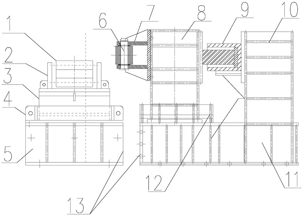
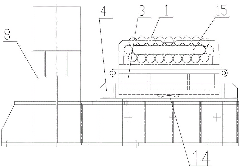
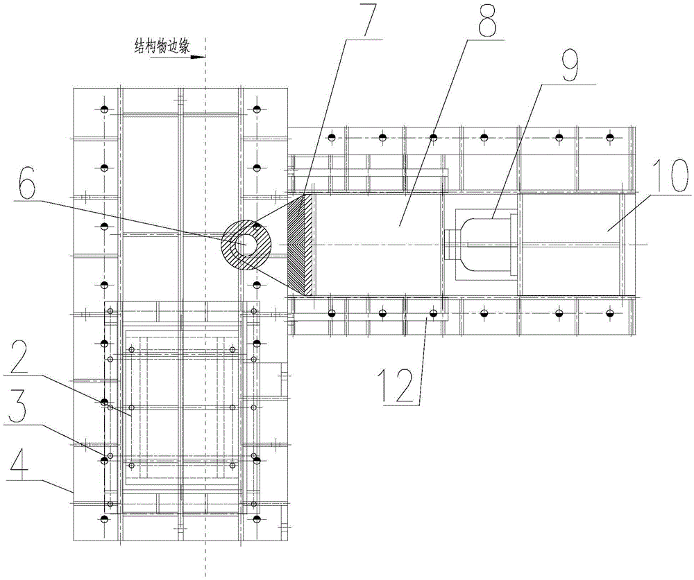
[0026] As shown in the accompanying drawings, a roller trolley device integrating traveling and limit adjustment functions includes a sliding device and a limit adjusting device arranged on the side of the sliding device. The sliding device includes a tackle 2 , a pad beam 3 arranged at the bottom of the tackle 2 , and a pallet 4 arranged at the bottom of the pad beam 3 . Described tackle 2 comprises U-shaped frame 16, main shaft 15, continuous crawler roller 1, and main shaft 15 is that cross-section is oval structure, and the two ends of main shaft 15 are welded and connected with the both sides of U-shaped frame 16, and continuous crawler roller 1 is A crawler structure composed of several horizontal rollers wraps around the outside of the main shaft 15 and can be rolled around the main shaft 15 for transmission. The backing beam 3 is fixedly...


PUM


Abstract

The invention discloses a rolling wheel trolley device integrating the traveling function with the limiting adjusting function. The device comprises a sliding device and a limiting adjusting device arranged on the side face of the sliding device. The sliding device comprises a pulley (2), a bearing beam (3) arranged on the lower portion of the pulley (2) and fixedly connected with the pulley (2), and a carrying frame (4) arranged on the lower portion of the bearing beam (3). A horizontal adjusting mechanism (14) is arranged between the carrying frame (4) and the bearing beam (3). The bearing beam (3) pitches and swings through the horizontal adjusting mechanism (14), and continuous track type rolling wheels (1) are arranged on the upper portion of the pulley (2). The limiting adjusting device comprises a jack (9) used for transverse adjustment, a movable jack force transmission base (8) and a limiting adjusting rolling wheel (6) arranged at the front end of the movable jack force transmission base (8), and the jack (9) and the limiting adjusting rolling wheel (6) are in transmission connection through the movable jack force transmission base (8).

Description

technical field [0001] The invention relates to a roller trolley device integrating the functions of running and limit adjustment, and is a mechanical device for pushing or dragging structures to target positions. The invention also discloses a method for pushing / dragging a structure by using the roller trolley device. Background technique [0002] With the development of my country's railways, highways, and municipal engineering construction, there are more and more bridge structures across railways, highways, and rivers, and the use of push / drag construction of bridge structures is becoming more and more common. Comprehensively considering that the slides used in the push / drag construction are mostly walking automatic push equipment, steel structure flat slides and roller trolley slides. In the above-mentioned construction, the walking-type automatic jacking equipment is expensive, the construction speed is slow, and the construction period is long; the steel structure fl...

Claims


Application Information

Patent Timeline
IPC IPC(8): E01D21/06E04G21/16
CPCE01D21/06E04G21/16
Inventor 杨基好张延军高步廷仲亚斌杨淑华苗野孟勇
Owner 中铁十局集团有限公司
Learn More