Construction method

A technology of construction method and fixing method, which is applied to building components, walls, buildings, etc., can solve the problems of insurmountable pendulum movement of unit panels, loss of horizontal support force, and collision of unit panels with the floor, etc., to avoid operation risks, hoisting Process stabilization, the effect of slowing down the pendulum movement

Active Publication Date: 2017-12-12
JIANGSU JIAZE CONSTR CO LTD
View PDF8 Cites 0 Cited by
  • Summary
  • Abstract
  • Description
  • Claims
  • Application Information

AI Technical Summary

Problems solved by technology

[0006] This construction method also has disadvantages. It is that, in order to ensure that the hoisted unit panels can be freely transported up and down and that the unit panels do not collide with the floor, the spreader must be installed at a certain distance from the floor, and the operator can only Stand on the lifting floor to support the unit slab, so there is a horizontal distance between the lifting point on the top of the unit slab and the support point of the operator on the bottom of the unit slab, so even if the operator releases the support to the unit slab at the extreme position close to the edge of the floor, The unit plate still loses the horizontal support force of the operator in an instant in the tilted state, and swings outward under the action of gravity, making a pendulum motion in the air, which makes the operator as close as possible to the edge of the lifting floor, increasing the potential for falling. At the same time, the pendulum movement of the unit plate is difficult to overcome, and there are risks such as the unit plate colliding with the floor and falling, which increases the safety hazard of working at heights

Method used


Image

  • Construction method
  • Construction method
  • Construction method

Examples


Embodiment 1

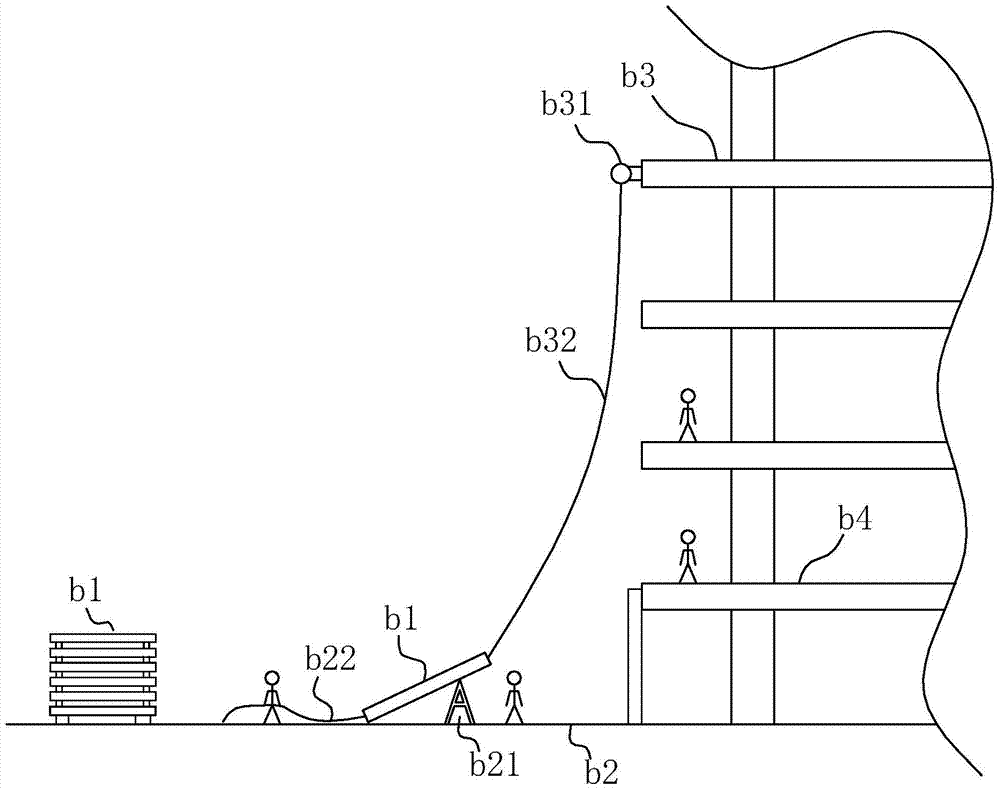
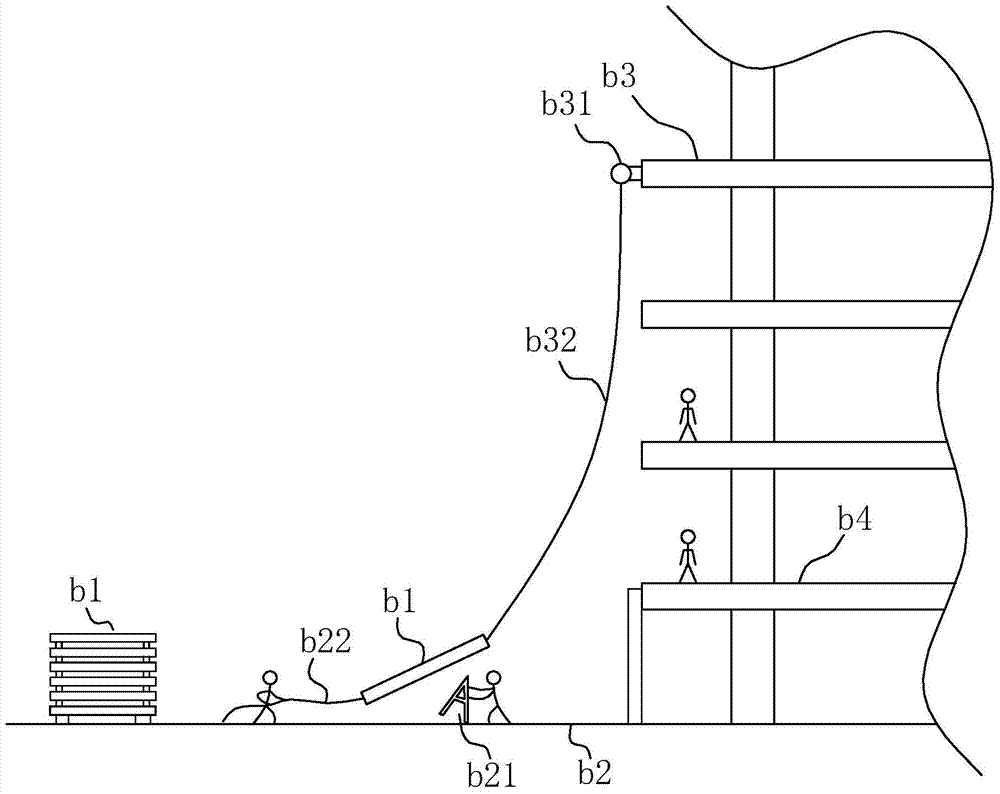
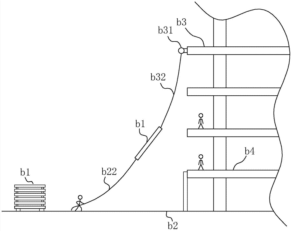
[0048] Such as Figure 10 As shown, configure a truck b5, the outward end of the fork 1 is the front end 11, and the inward end is the rear end 12, the truck b5 is pushed to the edge of the lifting layer b2, the front end 11 is facing outward and the fork 1 and the The edge is vertical, and at the same time, make the front end 11 equal to the edge position of the lifting layer b2 or exceed or be less than 10cm. At this time, record the positioning point 6 at the lateral position of the rear end 12 of the fork 1, and measure the positioning point 6 to the lifting layer with a tape measure The vertical distance from the edge of b2 and recorded as L1.

[0049] Such as Figure 13 As shown, the spreader b31 is installed outside the floor of the spreader layer b3. The spreader b31 can use an electric hoist or a crane. Measure the vertical distance between the rope entry and exit point 7 of the spreader b31 and the floor and record it as L2. Figure 10 shows the unit plate b1 hangi...

Embodiment 2

[0055] The difference between the second embodiment and the first embodiment is that the fixing method of the transport vehicle b5 can be controlled or fixed by the operator, and this embodiment can be adopted when the unit board b1 to be installed is relatively light in weight


PUM


Abstract

Provided is a construction method and a carrier. A linear sliding rail and a sliding gasket pad part are additionally arranged on the carrier, the existing operation process of supporting unit plates by operators is replaced. The unit plates continuously bear supporting force of the linear sliding rail and the sliding pad part in the transition process that the unit plates become inclined from horizontal and then become vertical again, operation risks due to the fact that the operators are too close to the edge of a hoisting layer are avoided, meanwhile, pendulum motion generated when the operators instantly release the unit plates in the traditional hoisting process is buffered, the hoisting process of the unit plates is stable, and convenience and reliability are achieved.

Description

technical field [0001] The invention relates to a construction method, in particular to a construction method for unit curtain wall installation. Background technique [0002] Unitized curtain wall refers to the basic unit of complete curtain wall structure made in the factory by various wall panels and supporting frames. With the development of high-rise buildings, the unitized curtain wall has been more and more used due to its centralized mass production in the factory and the convenience of installation. [0003] In the prior art, the construction method of installing the unitized curtain wall outside the floor is as follows: Figures 1 to 4 As shown, the unit panel b1 is stacked in the safe area of ​​the construction site. At this time, the ground is the hoisting layer b2. The unit panel b1 is transported to the lifting site by a forklift, and erected on the bracket b21, making it in an inclined shape with the top facing upward. , install the spreader b31 outside the f...

Claims


Application Information

Patent Timeline
Patent Type & Authority Patents(China)
IPC IPC(8): E04G21/14E04B2/88
CPCE04B2/88E04G21/14
Inventor 费文桥
Owner JIANGSU JIAZE CONSTR CO LTD
Why Eureka
Try Eureka