Vehicle Braking Cruise Control Method Using Engine Braking System

A technology of engine braking and cruise control, which is applied in engine control, machine/engine, mechanical equipment, etc., can solve the problems of increased driver work intensity, increased unsafe driving downhill, and lowered driving intensity, so as to reduce labor intensity , Improving the effect of vehicle driving safety

Active Publication Date: 2018-08-07
WEICHAI POWER CO LTD
View PDF5 Cites 0 Cited by
  • Summary
  • Abstract
  • Description
  • Claims
  • Application Information

AI Technical Summary

Problems solved by technology

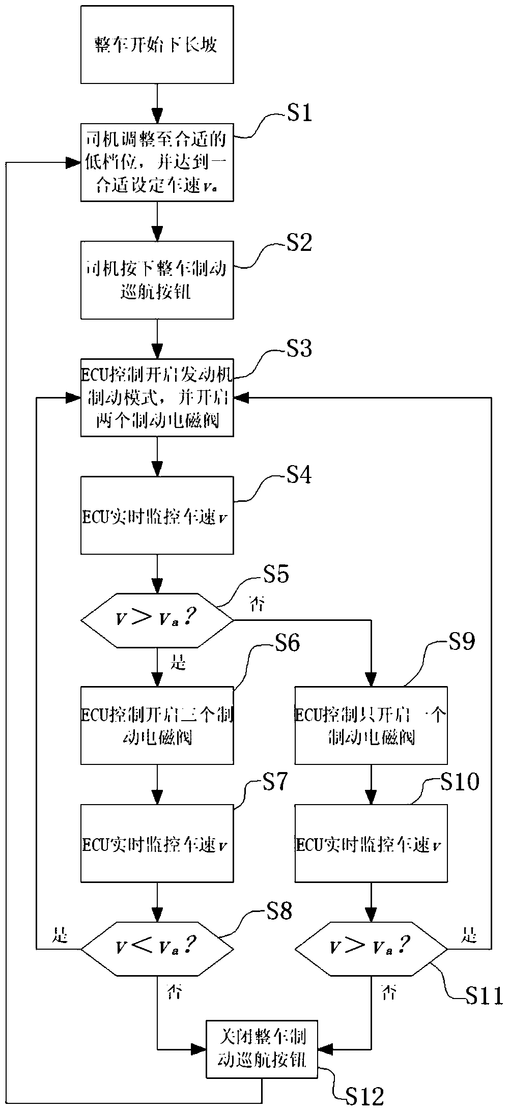
[0003] like figure 1 As shown, the existing control process when the whole vehicle goes down a long slope is as follows: the whole vehicle starts to go down a long slope——the driver puts in a certain gear and reaches an appropriate set speed——the driver presses the engine brake button of the whole vehicle ——ECU (Electronic Control Unit, Electronic Control Unit) controls to turn on the engine braking mode, and turn on all the brake solenoid valves ——The driver adjusts the gear according to the speed change or applies the service brake ——The vehicle speed is maintained at the set speed Nearby; however, when the vehicle goes down a long slope, the driver needs to select a gear for engine braking. If the selected gear is too low, the engine braking force will be large at the same speed, so the vehicle speed is often low; if the selected gear If it is too high, the engine braking force is insufficient at the same speed, and the driver needs to use the service brake frequently to reduce the vehicle speed. The movement also increases the driver's work intensity

Method used


Image

  • Vehicle Braking Cruise Control Method Using Engine Braking System
  • Vehicle Braking Cruise Control Method Using Engine Braking System
  • Vehicle Braking Cruise Control Method Using Engine Braking System

Examples


Embodiment Construction

[0030] The specific implementation manners of the present invention will be further described in detail below in conjunction with the accompanying drawings and embodiments. The following examples are used to illustrate the present invention, but are not intended to limit the scope of the present invention.

[0031] In the description of the present invention, it should be noted that the terms "first", "second", "third" and so on are only used for descriptive purposes, and should not be understood as indicating or implying relative importance.

[0032] In the description of the present invention, it should be noted that unless otherwise specified and limited, the terms "installation", "connection" and "connection" should be understood in a broad sense, for example, it can be a fixed connection or a detachable connection. Connected, or integrally connected; it may be mechanically connected or electrically connected; it may be directly connected or indirectly connected through an...


PUM


Abstract

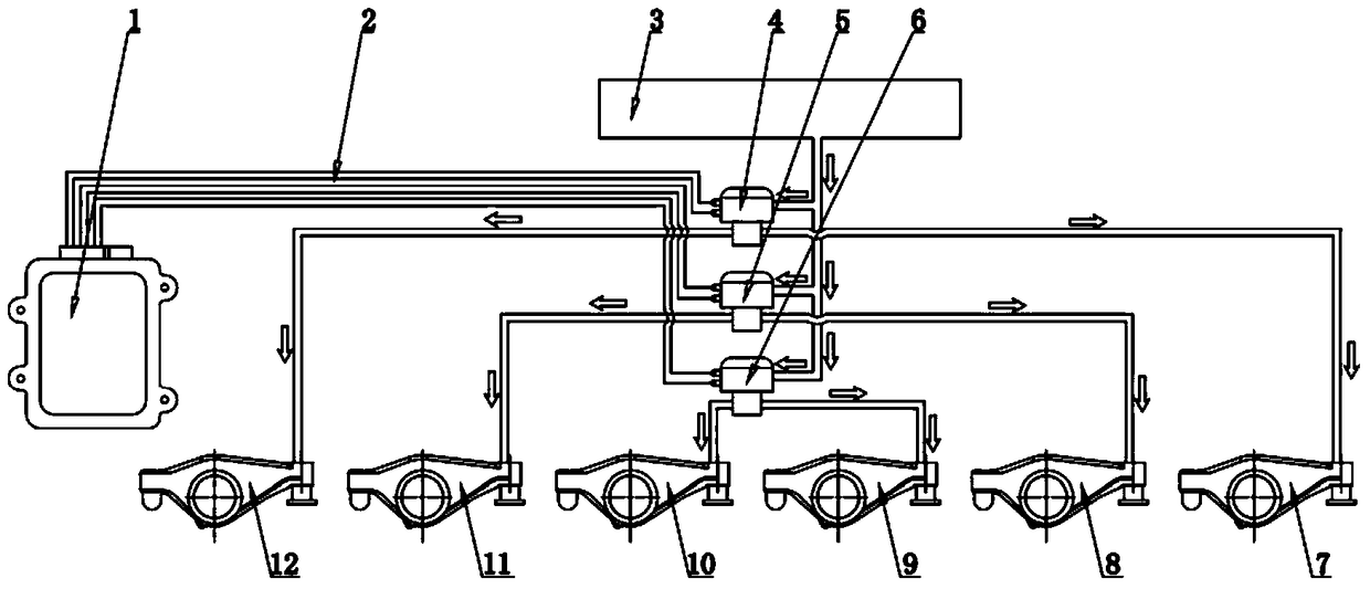
The invention relates to the technical field of whole vehicle braking and discloses an engine braking system. The engine braking system comprises an ECU, a main oil gallery, three braking electromagnetic valves and six braking rocker arms which corresponds to six air cylinders of an engine in a one-to-one mode. The ECU is connected with the three braking electromagnetic valves individually through braking electromagnetic valve wiring harnesses. An oil way of one braking electromagnetic valve communicates with two braking rocker arms. Oil ways of the three braking electromagnetic valves are connected to the main oil gallery. The invention further provides a whole vehicle braking cruise control method applying the engine braking system. According to the engine braking system and the whole vehicle braking cruise control method applying the engine braking system, the whole vehicle road safety during long downhill of a whole vehicle can be improved and the labor intensity of a driver is relieved.

Description

technical field [0001] The invention relates to the technical field of vehicle braking, in particular to a vehicle braking cruise control method using an engine braking system. Background technique [0002] At present, when most vehicles go down a long slope with a full load or a heavy load, the engine brake must be turned on in a certain gear, and combined with intermittent service brake to control the vehicle speed. Select the appropriate gear according to the vehicle load and other conditions, and apply appropriate service brakes according to the speed of the vehicle. [0003] Such as figure 1 As shown, the existing control process when the whole vehicle goes down a long slope is as follows: the whole vehicle starts to go down a long slope——the driver puts in a certain gear and reaches an appropriate set speed——the driver presses the engine brake button of the whole vehicle ——ECU (Electronic Control Unit, Electronic Control Unit) controls to turn on the engine braking m...

Claims


Application Information

Patent Timeline
Patent Type & Authority Patents(China)
IPC IPC(8): F02D13/06F02D29/02
CPCF02D13/06F02D29/02F02D2200/501
Inventor 黄国龙周帅刘冰姚敏胡亮
Owner WEICHAI POWER CO LTD
Why Eureka
Try Eureka