An Auxiliary Device for Maxwell Vacuum Gauge to Safely Measure the Vacuum Degree of Fuel Tank

An auxiliary device and vacuum gauge technology, which is applied in the field of transformer manufacturing, can solve the problems of polluting the body, product scrapping, mercury backflow, etc., and achieve the effects of increasing accuracy, reducing time spent, and preventing misoperation

Active Publication Date: 2018-09-28
CHINA XD ELECTRIC CO LTD
View PDF3 Cites 0 Cited by
  • Summary
  • Abstract
  • Description
  • Claims
  • Application Information

AI Technical Summary

Problems solved by technology

[0002] In the process of transformer manufacturing, in order to ensure the quality of product manufacturing and the stability of operation, it is necessary to vacuumize the oil tank; and the most commonly used instrument for measuring the degree of vacuum is the Maxwell vacuum gauge (rotary compression vacuum gauge). It can directly measure the pressure value of the fuel tank; but due to its design structure and the medium (mercury) used, if it is not properly operated when measuring the vacuum degree (use process: after connecting the Maxwell vacuum gauge to the fuel tank, slowly Rotate it to the upright state, read the vacuum value according to the mercury liquid level difference; immediately return it to the lying state after the measurement), it is very easy for the mercury in the instrument to flow back into the transformer oil tank and pollute the body, resulting in the product being scrapped ; In order to meet the safe measurement of the vacuum degree of the fuel tank, a new type of McFarland vacuum gauge auxiliary device must be designed, which can not only meet the measurement of the vacuum degree of the fuel tank, but also eliminate the hidden danger of mercury backflow

Method used


Image

  • An Auxiliary Device for Maxwell Vacuum Gauge to Safely Measure the Vacuum Degree of Fuel Tank
  • An Auxiliary Device for Maxwell Vacuum Gauge to Safely Measure the Vacuum Degree of Fuel Tank
  • An Auxiliary Device for Maxwell Vacuum Gauge to Safely Measure the Vacuum Degree of Fuel Tank

Examples


Embodiment Construction

[0023] The present invention will be further described in detail below in conjunction with the accompanying drawings and specific embodiments.

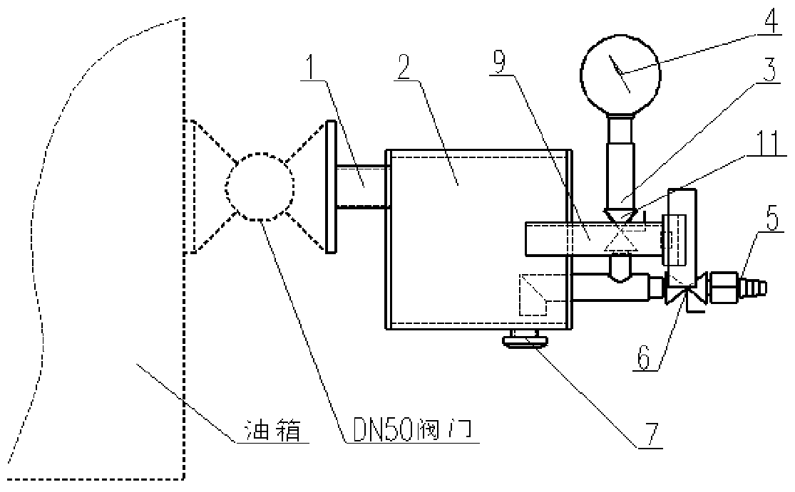
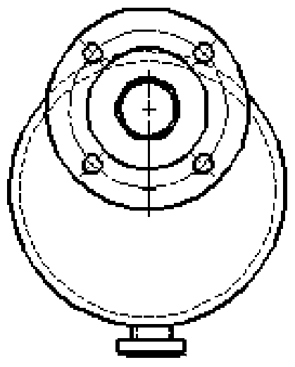
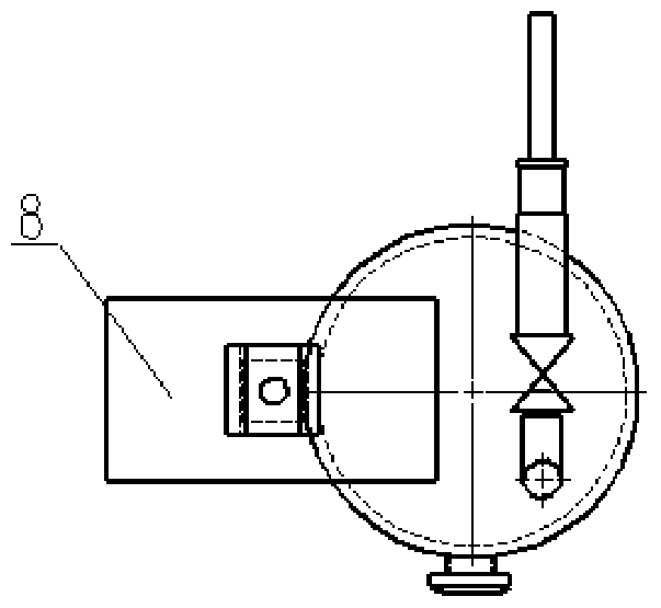
[0024] Such as Figure 1 to Figure 4 As shown, the present invention is an auxiliary device for a Maxwell vacuum gauge for safely measuring the vacuum degree of an oil tank, comprising a pipe joint 1 with a live flange, a box body 2, a Maxwell vacuum gauge bracket 9, a vacuum pressure gauge 4, and a Maxwell vacuum gauge Meter 8 and conversion joint 10; Wherein,

[0025] A pipe joint 1 with a live flange is installed on one side of the box body 2, and is used to connect with the oil tank that needs to measure the vacuum degree;

[0026] The McFarland vacuum gauge bracket 9 and the transition pipe 10 are installed on the other side of the box body 2 relative to the pipe joint 1 with a live flange, and the McFarland vacuum gauge 8 is installed on the Maxwell vacuum gauge bracket 9, through the McFarland vacuum gauge The vacuum gauge su...


PUM


Abstract

A McLeod vacuum gauge auxiliary device for safely measuring the vacuum degree of an oil tank of the invention comprises a pipe joint with a loose flange, a box body, and the like. The pipe joint with a loose flange is mounted on one side of the box body, and is used for being connected with an oil tank of which the vacuum degree needs to be measured. A McLeod vacuum gauge bracket and a conversion connecting pipe are mounted on the other side, opposite to the pipe joint, of the box body. A McLeod vacuum gauge is mounted on the McLeod vacuum gauge bracket, and is driven by the McLeod vacuum gauge bracket to rotate. The conversion connecting pipe is connected with a vacuum pressure gauge through a vacuum measurement connecting pipe, and is connected with the McLeod vacuum gauge through a tower joint. The bottom of the box body is equipped with a plug. According to the invention, through use of the front-end loose flange and the conversion connecting pipe, the plug is always at the bottommost part of the device, and there is a height difference between the vacuum pumping position and the vacuum measuring position of the box body; mercury is effectively prevented from entering the oil tank when the mercury enters the device due to misoperation of the McLeod vacuum gauge; and the mercury entering the box body can be discharged through the plug at the bottom.

Description

Technical field: [0001] The invention belongs to the technical field of transformer manufacturing, and in particular relates to an auxiliary device for a Maxwell vacuum gauge for safely measuring the vacuum degree of an oil tank. Background technique: [0002] In the process of transformer manufacturing, in order to ensure the quality of product manufacturing and the stability of operation, it is necessary to vacuumize the oil tank; and the most commonly used instrument for measuring the degree of vacuum is the Maxwell vacuum gauge (rotary compression vacuum gauge). It can directly measure the pressure value of the fuel tank; but due to its design structure and the medium (mercury) used, if it is not properly operated when measuring the vacuum degree (use process: after connecting the Maxwell vacuum gauge to the fuel tank, slowly Rotate it to the upright state, read the vacuum value according to the mercury liquid level difference; immediately return it to the lying state af...

Claims


Application Information

Patent Timeline
Patent Type & Authority Patents(China)
IPC IPC(8): G01L21/06
CPCG01L21/06
Inventor 田子九胡宽海贾恩宁席卫华韩新利赵维涛
Owner CHINA XD ELECTRIC CO LTD
Why Eureka
Try Eureka