
Power Automatic Test System

A power automatic test and detection system technology, which is applied in the direction of power supply test, measuring power, measuring devices, etc., can solve the problems of test result validity discount, recording error, retention, etc., and achieve the effect of improving test efficiency and standardization

Active Publication Date: 2018-12-28
DONGGUAN GUANJIA ELECTRONICS EQUIP
View PDF11 Cites 0 Cited by
  • Summary
  • Abstract
  • Description
  • Claims
  • Application Information

AI Technical Summary

Problems solved by technology

At present, the test is difficult to meet the requirements of customers at different levels for the changing technical parameters of the product
[0004] 2. The product test is still stuck in the stage of non-automated operation, manual recording, and non-standardized calculation. The test instrument cannot play its due test effect. In addition, human-made recording errors and calculation errors greatly reduce the validity of the test results.
[0005] 3. This type of high-power switching power supply has no targeted professional standards, and there is no professional test guidance document. Therefore, in the actual test process, the test methods, operation steps, and test tools vary from person to person. The analysis and calculation process of the test data are also different, resulting in significant differences in test results
[0006] 4. Product upgrades rely on a large amount of data testing as a support, but in the manual testing stage, a large amount of process data has not been effectively recorded, and the targeted improvement of products cannot provide powerful test data, which will have a certain impact on industrialization upgrades
[0007] 5. At present, the test information of each instrument is relatively independent, and the interoperability of test data is not strong. In today’s rapid development of informatization, networked parameter testing, test data sharing and database-style storage will be the key to the query of test results. and access to provide greater convenience

Method used


Image

  • Power Automatic Test System
  • Power Automatic Test System
  • Power Automatic Test System

Examples


Embodiment Construction

[0045] The technical solutions in the embodiments of the present invention are clearly and completely described below in conjunction with the accompanying drawings in the embodiments of the present invention. Obviously, the described embodiments are only part of the embodiments of the present invention, not all of them. Based on the embodiments of the present invention, all other embodiments obtained by persons of ordinary skill in the art without making creative efforts belong to the protection scope of the present invention.

[0046] In the following description, a lot of specific details are set forth in order to fully understand the present invention, but the present invention can also be implemented in other ways different from those described here, and those skilled in the art can do it without departing from the meaning of the present invention. By analogy, the present invention is therefore not limited to the specific examples disclosed below.

[0047] Such as figure ...


PUM


Abstract

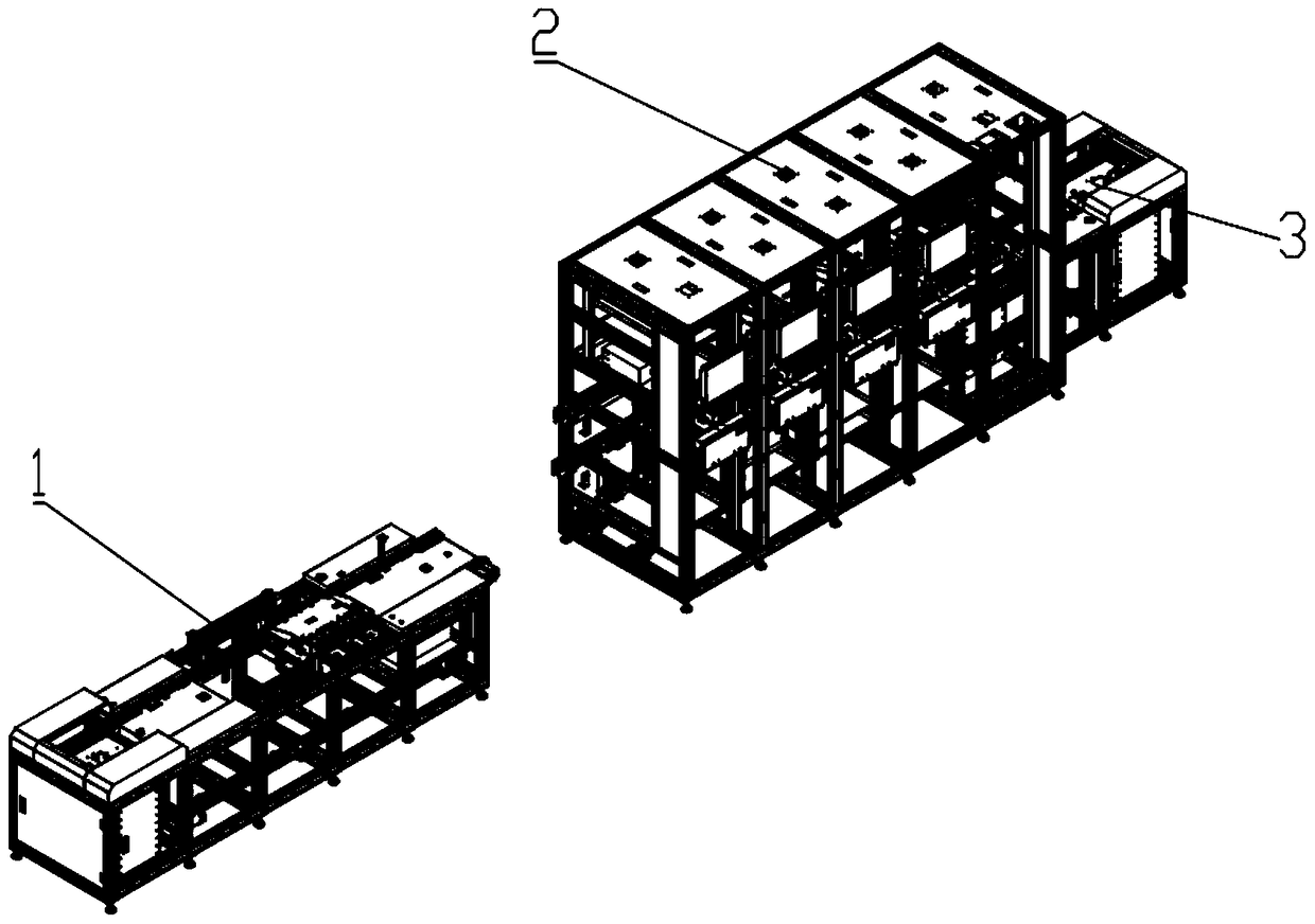
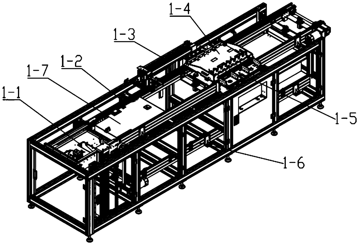
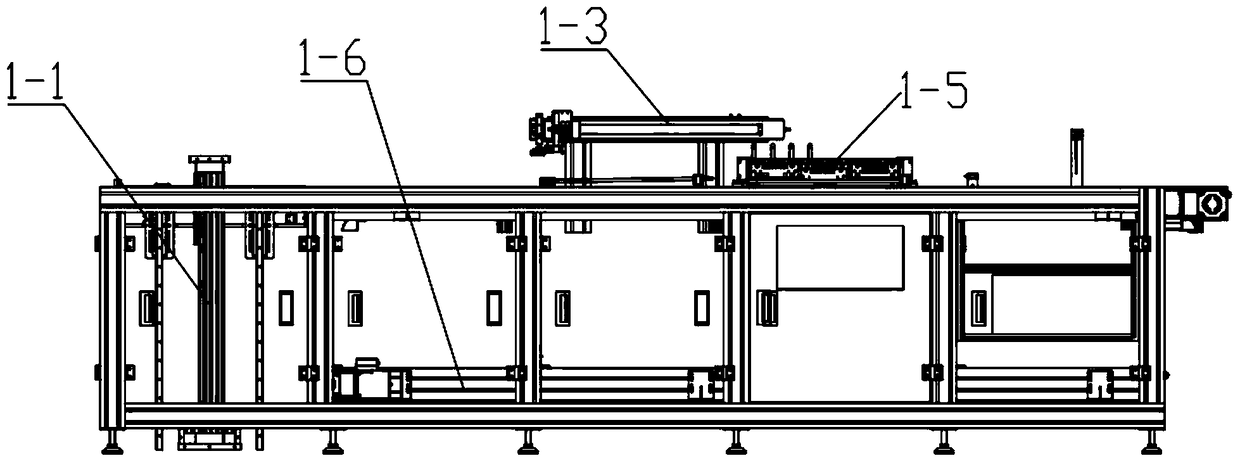
The present invention discloses a power supply automatic test system. The power supply automatic test system comprises a feeding system, a detection system and a discharge system which are arranged in order. The feeding system includes a jig in-position lifting mechanism, a first conveying chain and a code scanning mechanism which are arranged in order. The conveying directions of the first conveying chain and the second conveying chain are opposite, and the second conveying chain is configured to convey the jig having been tested to the jig in-position lifting mechanism. The detection system comprises a HI-POT detection device, an ATE detection device, a PE detection device and an AC end pull-out device which are arranged in the order from left to right. An upper conveying chain and a middle conveying chain are configured to convey the jig to pass through the HI-POT detection device, the ATE detection device, the PE detection device and the AC end pull-out mechanism in order. The discharge system is located at the tail end of the detection system, and a DC end pull-out mechanism for the jig of the detection system is configured to pull out the DC end of the supply power. The power supply automatic test system is capable of automated implementation of continuous test of all parameters of a power supply, improvement of test standardization and enhancement of test precision and test efficiency.

Description

technical field [0001] The invention relates to the technical field of power supply testing, in particular to an automatic power supply testing system. Background technique [0002] With continuous breakthroughs in power electronics technology, industrial high-power power supplies are developing in the direction of high-frequency efficiency, digitalization, modularization, and intelligence. The development of such power supplies pays more and more attention to power conversion efficiency, and the power density is becoming more and more high. In the application fields of this kind of power supply, such as monocrystalline silicon and sapphire industries, the requirements for technology are getting higher and higher, which makes the requirements for the performance index and control accuracy of the power supply itself are also getting higher and higher. However, most of the existing tests use specific test methods and platforms according to different product types. Today, with...

Claims


Application Information

Patent Timeline
Patent Type & Authority Patents(China)
IPC IPC(8): G01R31/01G01R31/40
Inventor 李驱虎
Owner DONGGUAN GUANJIA ELECTRONICS EQUIP
Learn More