Electronic equipment and control method
A technology of electronic equipment and controllers, which is applied in the field of control and can solve problems such as no vibration and weak vibration
- Summary
- Abstract
- Description
- Claims
- Application Information
AI Technical Summary
Problems solved by technology
Method used
Image

Examples
Embodiment 1
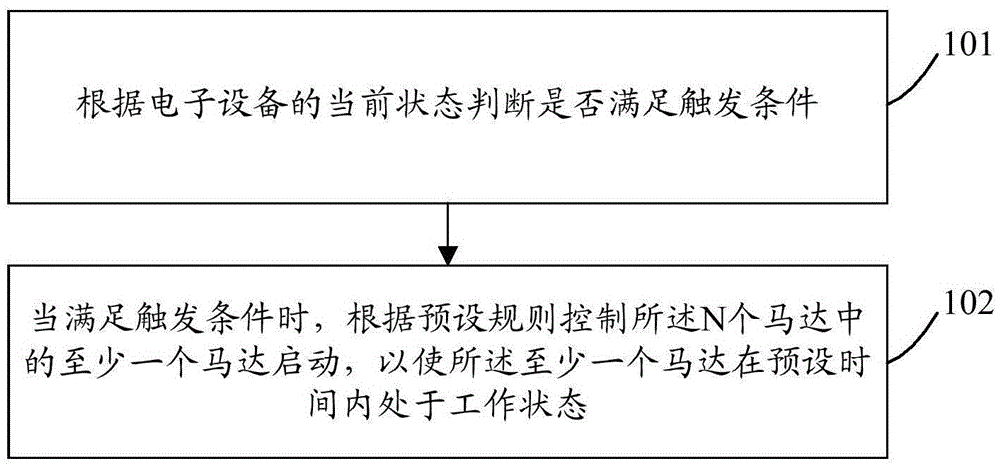
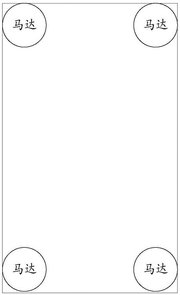
[0102] figure 1 Schematic diagram of the implementation flow of the control method provided by the present invention Figure 1 , used in electronic equipment, the electronic equipment includes N motors, N is a positive integer greater than or equal to 2, and the N motors are evenly distributed in the space of the electronic equipment. In a preferred embodiment of the present invention, the control The method mainly includes the following steps:
[0103] Step 101: Determine whether a trigger condition is met according to the current state of the electronic device.
[0104] Preferably, the judging whether the trigger condition is met according to the current state of the electronic device may include:
[0105] Determine whether the receiver of the electronic device receives a touch input;
[0106] If yes, it is determined that the trigger condition is met.
[0107] Step 102: When the trigger condition is met, at least one of the N motors is controlled to start according to a...
Embodiment 2
[0128] Figure 4 Schematic diagram of the implementation flow of the control method provided by the present invention Figure II , used in electronic equipment, the electronic equipment includes N motors, N is a positive integer greater than or equal to 2, and the N motors are evenly distributed in the space of the electronic equipment. In a preferred embodiment of the present invention, the control The method mainly includes the following steps:
[0129] Step 401: Determine whether a trigger condition is met according to the current state of the electronic device.
[0130] Preferably, the judging whether the trigger condition is met according to the current state of the electronic device may include:
[0131] Determine whether the receiver of the electronic device receives a touch input;
[0132] If yes, it is determined that the trigger condition is met.
[0133] Step 402: When the trigger condition is satisfied, determine the motor to be started according to the preset ...
Embodiment 3
[0154] Figure 7 Schematic diagram of the implementation flow of the control method provided by the present invention Figure three , used in electronic equipment, the electronic equipment includes N motors, N is a positive integer greater than or equal to 2, and the N motors are evenly distributed in the space of the electronic equipment. In a preferred embodiment of the present invention, the control The method mainly includes the following steps:
[0155] Step 701: Determine whether the receiver of the electronic device receives a touch input.
[0156] Here, the touch input may be a first type of input made on the input pad used as a keyboard input; it may also be a second type of input made on the input pad used as a track input.
[0157] Step 702: If yes, determine that the current state of the electronic device satisfies the trigger condition.
[0158] Step 703: When the trigger condition is satisfied, determine the motor to be started according to the preset rule.
...
PUM
 Abstract
Description
Claims
Application Information