
An Electromechanical Coupling Prediction Method for the Performance of Deformable Distributed Mems Phase Shifters

A technology of electromechanical coupling and prediction method, applied in the direction of instruments, electrical digital data processing, special data processing applications, etc., can solve the problems of high difficulty in process manufacturing, high manufacturing cost, and failure to consider whether the electrical parameters meet the requirements, etc.

Active Publication Date: 2018-08-28
XIDIAN UNIV
View PDF3 Cites 0 Cited by
  • Summary
  • Abstract
  • Description
  • Claims
  • Application Information

AI Technical Summary

Problems solved by technology

MEMS phase shifters involve interdisciplinary research, but currently researchers are researching distributed MEMS phase shifters from the perspective of a single discipline. There are two main methods: 1. Studying distributed MEMS phase shifters purely from a mechanical point of view, This research method can only improve the structure of the distributed MEMS phase shifter, and cannot consider whether the electrical parameters meet the requirements; The physical structure of the phase device only considers the circuit parameters, which will cause problems such as high manufacturing difficulty and high manufacturing cost.

Method used


Image

  • An Electromechanical Coupling Prediction Method for the Performance of Deformable Distributed Mems Phase Shifters
  • An Electromechanical Coupling Prediction Method for the Performance of Deformable Distributed Mems Phase Shifters
  • An Electromechanical Coupling Prediction Method for the Performance of Deformable Distributed Mems Phase Shifters

Examples


Embodiment Construction

[0072] The present invention will be further described below in conjunction with the accompanying drawings and embodiments.

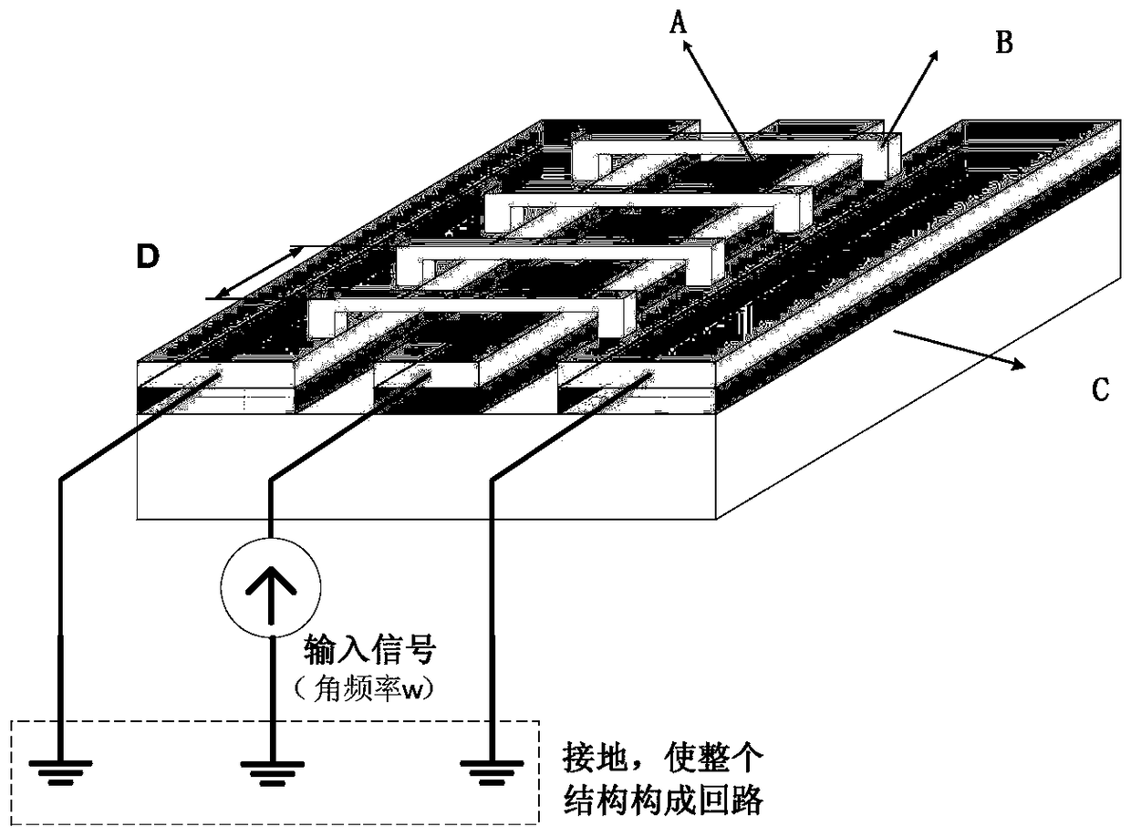
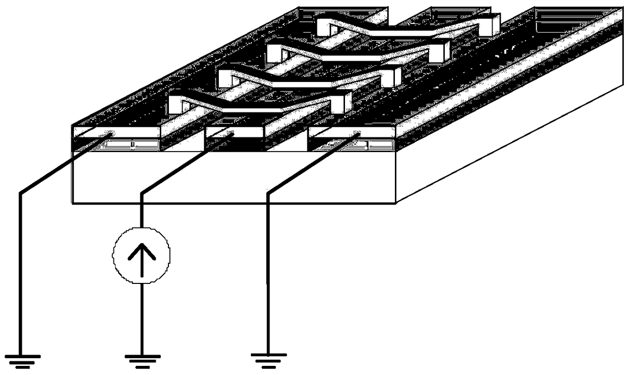
[0073] refer to figure 1 , the present invention is an electromechanical coupling prediction method for the performance of a deformed distributed MEMS phase shifter, and the specific steps are as follows:

[0074] Step 1, determine the structural parameters and electromagnetic working parameters of the distributed MEMS phase shifter.

[0075] The structural parameters of the distributed MEMS phase shifter are as follows figure 2 It includes the length, width and thickness of the coplanar waveguide transmission line, MEMS bridge and dielectric layer, as well as the distance between two adjacent bridges and the height of the MEMS bridge from the dielectric layer; the material properties of the distributed MEMS phase shifter, including the dielectric layer The relative permittivity of the distributed MEMS phase shifter; the electromagnetic operating par...


PUM


Abstract

The invention discloses an electromechanical coupling prediction method for the performance of a deformed distributed MEMS phase shifter. The method comprises the steps of 1) determining structure parameters, material attributes and electromagnetic working parameters of a distributed MEMS phase shifter; 2) determining equivalent circuit parameters of the distributed MEMS phase shifter; 3) determining a working environment condition; 4) performing mechanical analysis on a structure and extracting a maximum offset after structure deformation; 5) calculating the value of a variable capacitor composed of each MEMS bridge and a transmission line after structure deformation; 6) establishing an electromechanical coupling model of each MEMS bridge and calculating phase-shift magnitude; 7) calculating the phase-shift magnitude; and 8) judging whether the phase-shift magnitude of the phase shifter meets a requirement or not. The electromechanical coupling model for the structure parameters and the phase-shift magnitude of the distributed MEMS phase shifter, established with the method, can directly analyze the influence of the structure parameters on the phase-shift magnitude of the phase shifter, and can be used for quantitatively evaluating the influence of the structure deformation on the phase-shift magnitude of the distributed MEMS phase shifter in a load environment so as to guide the design and optimization of the distributed MEMS phase shifter.

Description

technical field [0001] The invention belongs to the technical field of microwave devices, in particular to an electromechanical coupling prediction method for the performance of a deformed distributed MEMS phase shifter. The electromechanical coupling model between the structural parameters of the distributed MEMS phase shifter and the phase shift amount established by the present invention can be used to directly analyze the influence of the structural parameters on the phase shift amount of the phase shifter, and guide the structural design and operation of the distributed MEMS phase shifter. optimization. Background technique [0002] With the development of RF MEMS (Micro-electromechanical Systems) technology, MEMS phase shifters have been widely used in various radar and satellite navigation fields due to their advantages of miniaturization, low loss, low cost, and good performance. Among them, the distributed MEMS phase shifter is easier to manufacture, smaller in siz...

Claims


Application Information

Patent Timeline
Patent Type & Authority Patents(China)
IPC IPC(8): G06F17/50
CPCG06F30/23
Inventor 王从思殷蕾王艳李娜周金柱李鹏保宏康明魁张逸群黄进唐宝富钟剑锋
Owner XIDIAN UNIV
Learn More