
Full-automatic laminating production line of transformer E-type iron cores

A fully automatic and transformer technology, applied in the manufacture of inductors/transformers/magnets, electrical components, circuits, etc., can solve the problems of high work intensity, low production efficiency, and sharp increase in labor costs, and achieve low iron column uniformity and structure Compact, versatile effects

Active Publication Date: 2016-05-04
CECEP ENVIRONMENTAL PROTECTION EQUIP CO LTD
View PDF5 Cites 33 Cited by
  • Summary
  • Abstract
  • Description
  • Claims
  • Application Information

AI Technical Summary

Problems solved by technology

[0003] The existing stacking process is completely manual stacking, manual stacking, high work intensity and frequent boring repetitive actions, low production efficiency and unstable product quality, coupled with the current sharp increase in labor costs, transformer companies urgently need a A fully automatic equipment that can replace manual lamination
[0004] At present, there are very few equipments for stacking E-type cores. Even if there are similar products, most of the stacked cores have process holes or rectangular silicon steel sheets, and the cores need to be pre-stacked manually, which cannot meet the needs of automatic feeding, automatic positioning and transmission. and automatic adjustment of the transformer window and the requirement of the step amount

Method used


Image

  • Full-automatic laminating production line of transformer E-type iron cores
  • Full-automatic laminating production line of transformer E-type iron cores

Examples


Embodiment 1

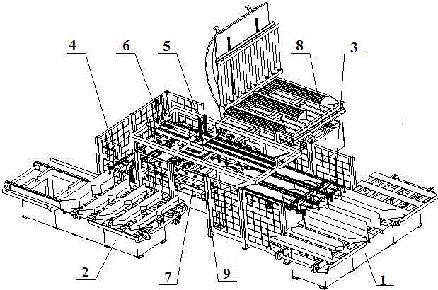
[0028] This embodiment provides a fully automatic stacking production line for transformer E-shaped cores, which includes a three-column feeding device 1 and a three-column transmission and positioning device 3 arranged in a straight line along the feeding direction of the side columns, and a three-column transmission and positioning device 3 sequentially arranged along the feeding direction of the yoke columns. The yoke column feeding device 2 and the yoke column transmission and positioning device 4 arranged in a straight line, the straight line where the three-column transmission and positioning device 3 is located is perpendicular to the straight line where the yoke column transmission and positioning device 4 is located, and the three-column transmission and positioning device 3 and the yoke column A receiving and output device 7 is provided between the transmission and positioning devices 4, and a three-column lamination device 5 and a yoke post lamination device 6 are arr...

Embodiment 2

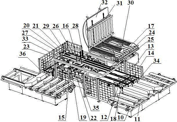
[0032] On the basis of embodiment 1, this embodiment provides a kind of figure 1 , 2 In the automatic stacking production line for transformer E-type iron cores shown, the three-column feeding device 1 includes a tray base 10 and a feeding tray 11, and a chain mechanism is provided on the tray base 10, and the chain mechanism is for feeding Pallet 11, on the feeding tray 11 there are alternately switched feeding stations and feeding stations, the feeding tray 11 is provided with a magnetic separation device, and the tray chassis 10 is provided with a lifting platform. The yoke column feeding device 2 is the same as the three-column feeding device 1 .

[0033] The three-column transmission positioning device 3 includes three groups of limit guide rails 12 parallel to the feeding direction of the side columns, a fixed-length transmission mechanism 13 arranged on the limit guide rails 12, and a pick-and-place mechanism located at the feed inlet of the fixed-length transmission m...

Embodiment 3

[0042] In the process of transformer stacking, some transformers need to have a stepping amount. In order to meet this requirement, on the basis of Embodiment 2, a third lead screw and nut pair 33 is also provided on the second stacking frame 23. The third The screw nut pair 33 is driven by a servo motor.

[0043] In this embodiment, on the frame 15, the first guide rail 24 and the second guide rail 25 are provided in parallel on both sides of the first servo electric slide table 17, and the third guide rail 26 and the second guide rail 26 are provided in parallel on both sides of the second servo electric slide table 21. Four guide rails 27, these four guide rails are auxiliary load-bearing rolling guide rail pairs.

[0044] Material receiving output device 7 is made up of electromagnetic frock, idler roller and chain that are located at the electromagnetic frock below. The electromagnetic tooling is used to bind the iron core, and the roller and chain are used to move out t...


PUM


Abstract

The invention provides a full-automatic laminating production line of transformer E-type iron cores. The full-automatic laminating production line comprises a three-column feeding device and a three-column transmission positioning device which are set to be a straight line along a side column feeding direction, and a yoke column feeding device and a yoke column transmission positioning device which are set to be a straight line along a yoke column feeding direction, wherein the straight line where the three-column transmission positioning device is is vertical to the straight line where the yoke column transmission positioning device is; a material receiving output device is arranged between the three-column transmission positioning device and the yoke column transmission positioning device; a three-column laminating device and a yoke column laminating device are arranged above the planes where the three-column transmission positioning device and the yoke column transmission positioning device are; the three-column laminating device and the yoke column laminating device are positioned on the same straight line, and are at the same position of the straight line where the three-column transmission positioning device is; one side of the material receiving output device is connected with an overturning device; and the material receiving output device and the overturning device are positioned on the same plane. The full-automatic laminating production line is time-saving, labor-saving, compact in structure and high in efficiency, the adjustability of a transformer window and step quantity can be realized, and the universality is high.

Description

technical field [0001] The invention belongs to the field of transformer iron core production, in particular to a fully automatic stacking production line for transformer E-type iron cores. Background technique [0002] The so-called "E" core means that three side columns and one yoke column are combined to form an E shape, and then the single layers of the core combined into an E shape are gradually stacked until the required thickness is reached. [0003] The existing stacking process is completely manual stacking, manual stacking, high work intensity and frequent boring repetitive actions, low production efficiency and unstable product quality, coupled with the current sharp increase in labor costs, transformer companies urgently need a A fully automatic equipment that can replace manual lamination. [0004] At present, there are very few equipments for stacking E-type cores. Even if there are similar products, most of the stacked cores have process holes or rectangular ...

Claims


Application Information

Patent Timeline
Patent Type & Authority Applications(China)
IPC IPC(8): H01F41/02
CPCH01F41/0233
Inventor 赵丹郭新安黄志方张智臻黄健许号永张华杰夏清普王平波
Owner CECEP ENVIRONMENTAL PROTECTION EQUIP CO LTD
Learn More