Gas flow measuring device and method based on ultrasonic bypass flow principle

A gas flow and ultrasonic technology, which is applied in the field of gas flow detection and the measurement of new measuring instruments, can solve the problems of decreased measurement accuracy, waterlogging of ultrasonic probes, test failure, etc., and achieves reduced requirements for uniformity of flow field and uniformity of flow field. Low requirements and simple structure

Inactive Publication Date: 2017-09-29
HUBEI RUIYI AUTOMATIC CONTROL SYST CO LTD
View PDF13 Cites 2 Cited by
  • Summary
  • Abstract
  • Description
  • Claims
  • Application Information

AI Technical Summary

Problems solved by technology

In addition, while measuring the gas flow, the ultrasonic flowmeter can also measure the composition at the same time for some occasions. For example, the document CN103454344A first proposed the application of the ultrasonic principle in China, which can solve the simultaneous measurement of gas composition and flow. However, the current ultrasonic Several challenges faced by gas flowmeters are: (1) In gases with high ultrasonic absorption, such as biogas with high concentration of CO2 and natural gas with high concentration of CO2, the ultrasonic signal is very small due to the energy absorption signal, which is easy to cause errors or even errors , the larger the pipe diameter, the more serious the problem
(2) When used in large pipe diameters, the uniformity of cross-sectional flow field distribution cannot be guaranteed, resulting in measurement errors. (3) When there is moisture condensation in the measurement pipeline, such as in the field of biogas, when measuring the biogas coming out of the fermentation tank, due to moisture condensation If the problem cannot be eliminated in time, it will cause waterlogging of the ultrasonic probe, resulting in a decrease in measurement accuracy or even test failure.
[0003] Through the analysis of the existing technology, it is found that the advantages of using ultrasonic technology to measure gas flow are obvious (wide range ratio, small pressure resistance, and can also measure components, etc.), but there is an urgent need to solve the application of ultrasonic gas measurement technology in high-moisture gases such as biogas components. Measurement field, as well as gas flow test problems in the field of large pipe diameter, high ultrasonic energy absorption gas, etc.

Method used


Image

  • Gas flow measuring device and method based on ultrasonic bypass flow principle
  • Gas flow measuring device and method based on ultrasonic bypass flow principle
  • Gas flow measuring device and method based on ultrasonic bypass flow principle

Examples


Embodiment 1

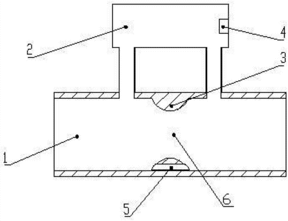
[0045] A gas flow detection device based on the principle of ultrasonic side flow, including a main pipeline 1 and a side flow pipeline 2, the main pipeline 1 communicates with the side flow pipeline 2, the side flow pipeline 2 is located on one side or the upper part of the main pipeline 1, along the The inner wall of the main pipe 1 is provided with two flow blocking elements 3 symmetrically up and down, and the side flow pipe 2 is provided with an ultrasonic sensor 4. The main pipe 1, the side flow pipe 2 and the flow blocking elements 3 together form a detection airway.

[0046] Two arc-shaped or square or trapezoidal baffles are axially arranged on the inner side of the main pipe 1, as attached figure 1 -3 shown.

[0047] Drain holes or grooves 5 are opened at the baffle 3 at the bottom of the main pipeline 1, as shown in A, B, C, and D in the accompanying drawing 8. One drainage hole or groove can be provided, and E and F can also be provided in the accompanying drawings...

Embodiment 2

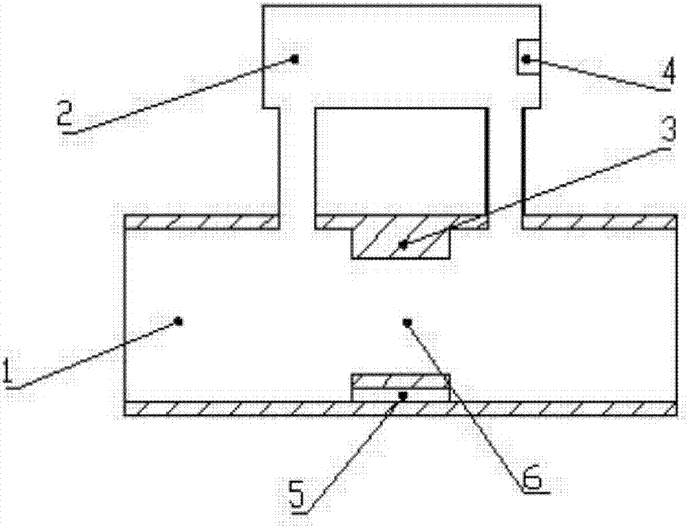
[0066] A gas flow detection device based on the principle of ultrasonic side flow, including a main pipeline 1 and a side flow pipeline 2, the main pipeline 1 communicates with the side flow pipeline 2, the side flow pipeline 2 is located on one side or the upper part of the main pipeline 1, along the The inner wall of the main pipe 1 is provided with two flow blocking elements 3 symmetrically up and down, and the side flow pipe 2 is provided with an ultrasonic sensor 4. The main pipe 1, the side flow pipe 2 and the flow blocking elements 3 together form a detection airway.

[0067] Two arc-shaped or square or trapezoidal baffles are axially arranged on the inner side of the main pipe 1, as attached figure 1 -3 shown.

[0068] Ultrasonic sensor 4 can be set as shown in accompanying drawing 7: A: direct-ray type, B: X type (0 ° < θ < 180 °), C: V type (0 ° < θ < 90 °), D: W Type (0°<θ<90°).

[0069] The measurement steps are:

[0070] A. Through the bypass pipeline 2 and the...

Embodiment 3

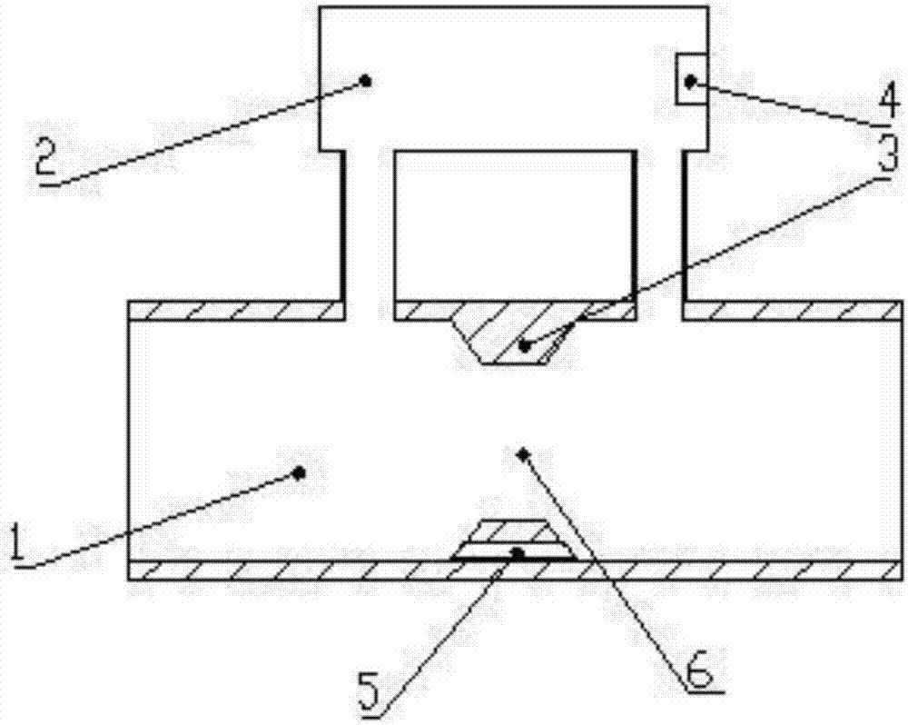
[0085] as attached Figure 4 , 5 As shown: part of the side flow pipe 2 is used as a flow blocking element 3 and is arranged in the main pipe 1 , and an ultrasonic sensor 4 is arranged in the side flow pipe 2 .

[0086] as attached Image 6 As shown: the side flow pipeline 2 is located on one side of the main pipeline 1, and several densely arranged flow blocking elements 3 are arranged along the parallel direction of the airflow of the main pipeline 1. The flow blocking elements 3 are several small pipes with open ends, as shown in the attached Shown in A and B of Fig. 9;

[0087] The spoiler 3 can also be arranged in a comb shape, as shown in C and D of FIG. 9 .


PUM


Abstract

The invention relates to the field of gas flow detection, in particular to a gas flow measuring device and method based on an ultrasonic bypass flow principle and belongs to the field of novel metering instrument measurement. The device comprises a main pipeline and a bypass flow pipeline. The main pipeline is communicated with the bypass flow pipeline, the bypass flow pipeline is located on the side face of the main pipeline, a current blocking part is arranged in the main pipeline, a current limiting channel is formed, and an ultrasonic sensor is arranged in the bypass flow pipeline. A detection gas way is formed by the main pipeline, the bypass flow pipeline and the current blocking part jointly. By means of the method of flow division on the main pipeline, the current blocking part is arranged in the main pipeline, the monotone increasing relationship between the time difference value and the standard flow in the bypass flow pipeline is determined, the gas flow is tested, water and corrosion problems can be effectively solved, and accurate measurement of large-pipe-diameter gas flow can be achieved.

Description

technical field [0001] The invention relates to the field of gas flow detection, in particular to a gas flow detection device and method based on the principle of ultrasonic side flow, and belongs to the field of new metering instrument measurement. Background technique [0002] At present, in the measurement of gas flow, the corrosion of gas, the interference of moisture condensation, the inhomogeneity of gas flow field with large diameter, and the adaptability of gas over-range are different challenges faced by different gas flow measurement principles. Differential pressure gas flowmeter: The measurement accuracy is generally low, the measurement range is narrow, the requirements for the straight pipe section on site are high, the pressure loss is too large, and the over-range may even damage the measuring element, and the corrosive gas also has the risk of corroding the differential pressure element; Vortex street gas flowmeter: the range is relatively small, greatly aff...

Claims


Application Information

Patent Timeline
Patent Type & Authority Applications(China)
IPC IPC(8): G01F1/66
CPCG01F1/66
Inventor 熊友辉吴俊宋礼攀石平静
Owner HUBEI RUIYI AUTOMATIC CONTROL SYST CO LTD
Why Eureka
Try Eureka