Fuel cell equipment and fuel cell energy system

A fuel cell and energy system technology, applied in the direction of fuel cells, fuel cell additives, fuel cell heat exchange, etc., can solve the problem of high energy consumption of heat tracing and heat preservation devices, and achieve the effect of less energy consumption

Active Publication Date: 2016-05-04
中国东方电气集团有限公司
View PDF9 Cites 8 Cited by
  • Summary
  • Abstract
  • Description
  • Claims
  • Application Information

AI Technical Summary

Problems solved by technology

[0005] The main purpose of the present invention is to provide a fuel cell device and a fuel cell energy system to solve the problem of high energy consumption of the heat tracing and heat preservation device of the fuel cell device in the prior art

Method used


Image

  • Fuel cell equipment and fuel cell energy system
  • Fuel cell equipment and fuel cell energy system
  • Fuel cell equipment and fuel cell energy system

Examples


Embodiment Construction

[0035] It should be noted that, in the case of no conflict, the embodiments in the present application and the features in the embodiments can be combined with each other. The present invention will be described in detail below with reference to the accompanying drawings and examples.

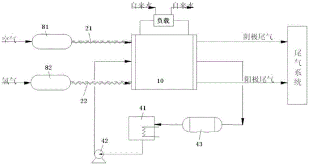
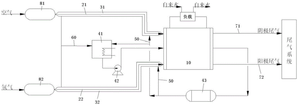
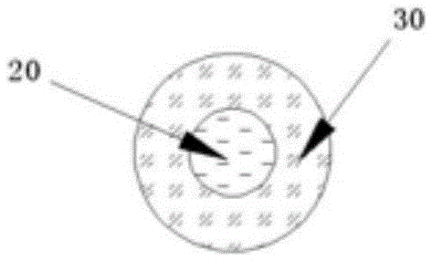
[0036] According to one aspect of the present invention, there is provided a fuel cell device, such as figure 2 In the illustrated embodiment, the fuel cell device includes: an electric stack 10; a reactant input pipe 20 connected to the electric stack 10 to input reactants; a heat exchange pipe 30 arranged in parallel with at least a part of the reactant input pipe 20, And the flow passage in the heat exchange tube 30 is separated from the flow passage in the reactant input pipe 20 by a partition; the first heat conduction part connects the electric stack 10 and the heat exchange pipe 30 to transfer the waste heat generated by the electric stack 10 to Heat exchange tube 30.

[0037] The fue...


PUM


Abstract

The invention provides fuel cell equipment and a fuel cell energy system. The fuel cell equipment comprises a galvanic pile, a reactant input pipe, a heat exchange pipe and a first heat-conducting part, wherein the reactant input pipe is connected with the galvanic pile to input a reactant; the heat exchange pipe and at least one part of the reactant input pipe are arranged in parallel; a flow channel in the heat exchange pipe is separated from the flow channel in the reactant input pipe through a first partition wall; and the first heat-conducting part is connected to the galvanic pile and the heat exchange pipe to transfer waste heat generated by the galvanic pile to the heat exchange pipe. The heat exchange pipe of the fuel cell equipment is used for carrying out heat exchange with the reactant input pipe while the first heat-conducting part transfers the waste heat generated by the galvanic pile to the heat exchange pipe, so that the heat exchange pipe transfers the waste heat generated by the galvanic pile to the reactant input pipe to keep the temperature of the reactant input pipe and the reactant in the reactant input pipe; the condition that moisture condensation affects smooth transportation of the reactant or causes water logging of the galvanic pile due to an over-low temperature is avoided; and in addition, the fuel cell equipment is low in energy consumption, and plays roles in energy conservation and environmental protection.

Description

technical field [0001] The invention relates to the field of fuel cells, in particular to a fuel cell device and a fuel cell energy system. Background technique [0002] A fuel cell is a power generation device that directly converts chemical energy stored in fuel and oxidant into electrical energy. Since it is not limited by the Carnot cycle, its direct power generation efficiency can be as high as more than 45%. It is environmentally friendly, high energy conversion efficiency, Long service life and other characteristics have broad application prospects in the fields of aerospace, submarines, electric vehicles, power stations, mobile devices, and households. Taking the proton exchange membrane fuel cell (PEMFC) as an example, the core power generation module of the battery, the stack, is composed of several single cells in series, and the single cell is composed of membrane electrodes, anode plates and cathode plates (or bipolar plates) to form a sandwich structure. Among...

Claims


Application Information

Patent Timeline
Patent Type & Authority Applications(China)
IPC IPC(8): H01M8/04014H01M8/04119H01M8/0606H01M8/0662H01M8/1007
CPCH01M8/04014H01M8/04067H01M8/04126H01M8/0606H01M8/0662H01M8/10Y02E60/50
Inventor 宋亚婷汤浩杨海玉刘志伟
Owner 中国东方电气集团有限公司
Why Eureka
Try Eureka