Wireless charging device, user terminal and wireless charging method

A wireless charging and user terminal technology, applied in circuit devices, electrical components, etc., can solve the problems of high implementation cost, high radiation, and insufficient charging distance, and achieve the effect of increasing the distance range, increasing the amount of infrared light, and improving charging efficiency.

Active Publication Date: 2016-05-04
YULONG COMPUTER TELECOMM SCI (SHENZHEN) CO LTD
View PDF6 Cites 6 Cited by
  • Summary
  • Abstract
  • Description
  • Claims
  • Application Information

AI Technical Summary

Problems solved by technology

In addition, magnetic induction wireless charging can only charge one-to-one, and it is impossible for one charging device to charge multiple user terminals at the same time, and the charging efficiency is low
Although the magnetic resonance wireless charging can realize one charging device to charge multiple user terminals at the same time, the distance between the user terminal and the charging device is greatly improved compared with the magnetic induction wireless charging technology. However, the magnetic resonance The traditional wireless charging also has problems such as low efficiency, insufficient charging distance, and high radiation, and the rechargeable charging device has an impact on the radiation efficiency of the user terminal antenna.
In addition, magnetic resonance wireless charging requires a separate communication module to establish a communication connection between the sending device and the receiving device, resulting in high implementation costs

Method used


Image

  • Wireless charging device, user terminal and wireless charging method
  • Wireless charging device, user terminal and wireless charging method
  • Wireless charging device, user terminal and wireless charging method

Examples


Embodiment Construction

[0031] The following will clearly and completely describe the technical solutions in the embodiments of the present invention with reference to the accompanying drawings in the embodiments of the present invention. Obviously, the described embodiments are only some, not all, embodiments of the present invention. Based on the embodiments of the present invention, all other embodiments obtained by persons of ordinary skill in the art without making creative efforts belong to the protection scope of the present invention.

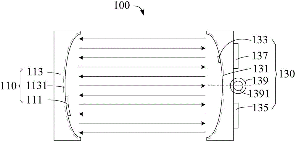
[0032] see figure 1 , the first embodiment of the present invention provides a wireless charging device 100 , including an infrared light emitting component 110 and an infrared light receiving component 130 . The infrared light emitting component 110 includes a light source component 111 and a reflective component 113, the light source component 111 is used to emit infrared light, the reflective component 113 is provided with a reflective mirror surface 1131 o...


PUM


Abstract

The invention provides a wireless charging method comprising the steps that infrared light emitted by an infrared light emitting module is received by a receiving mirror surface; the illumination intensity and the incident angle of infrared light received by the receiving mirror surface are sensed; an optimal receiving angle is determined according to the illumination intensity and the incident angle of infrared light; the receiving mirror surface is driven to rotate to the optimal receiving angle; and infrared light received by the receiving mirror surface is converted into charging electric energy so as to charge a user terminal. Besides, the invention also provides a wireless charging device applying the method and the user terminal. According to the wireless charging method, distance range of wireless charging can be increased so that synchronous charging of multiple user terminals can be realized, and charging efficiency can be enhanced.

Description

technical field [0001] The present invention relates to the field of wireless charging, in particular to a wireless charging device, a user terminal and a wireless charging method. Background technique [0002] The existing wireless charging technologies mainly include magnetic induction wireless charging and magnetic resonance wireless charging. Among them, the magnetic induction wireless charging uses the electromagnetic induction between the receiving coil and the transmitting coil to realize energy transfer, and the transfer efficiency is directly related to the coupling degree of the two coils. Therefore, the charging distance of magnetic induction wireless charging is very short, and it is necessary to ensure the precise alignment of the user terminal and the charging device to achieve efficient energy transmission. In addition, magnetic induction wireless charging can only charge one-to-one, and it is impossible for one charging device to charge multiple user termina...

Claims


Application Information

Patent Timeline
Patent Type & Authority Applications(China)
IPC IPC(8): H02J50/90
Inventor 吴聚章丁兆刚
Owner YULONG COMPUTER TELECOMM SCI (SHENZHEN) CO LTD
Why Eureka
Try Eureka