Radar apparatus

a technology of radar and distance measurement, which is applied in the direction of instruments, measurement devices, and using reradiation, etc., can solve the problem of reducing the distance measurement accuracy of targets trb>1/b>-trb>3

Active Publication Date: 2015-12-22
PANASONIC INTELLECTUAL PROPERTY MANAGEMENT CO LTD
View PDF22 Cites 3 Cited by
  • Summary
  • Abstract
  • Description
  • Claims
  • Application Information

AI Technical Summary

Benefits of technology

[0035]The radar apparatus according to the invention can make a measurement time that is necessary for a measurement involving plural measurement distance ranges shorter than in conventional cases while increasing the measurement distance range by suppressing inter-code interference, if any, due to mixing of reflection waves of a transmission code having a short transmission cycle into a signal in the ensuing, long transmission cycle.

Problems solved by technology

If the pulse compression radar apparatus 1z does not have a proper reception dynamic range, the peak level lowers and the range sidelobe level increases when pulse compression is done, resulting in reduction in the measurement accuracy of distances of the targets TR1-TR3.

Method used


Image

  • Radar apparatus
  • Radar apparatus
  • Radar apparatus

Examples


embodiment 1

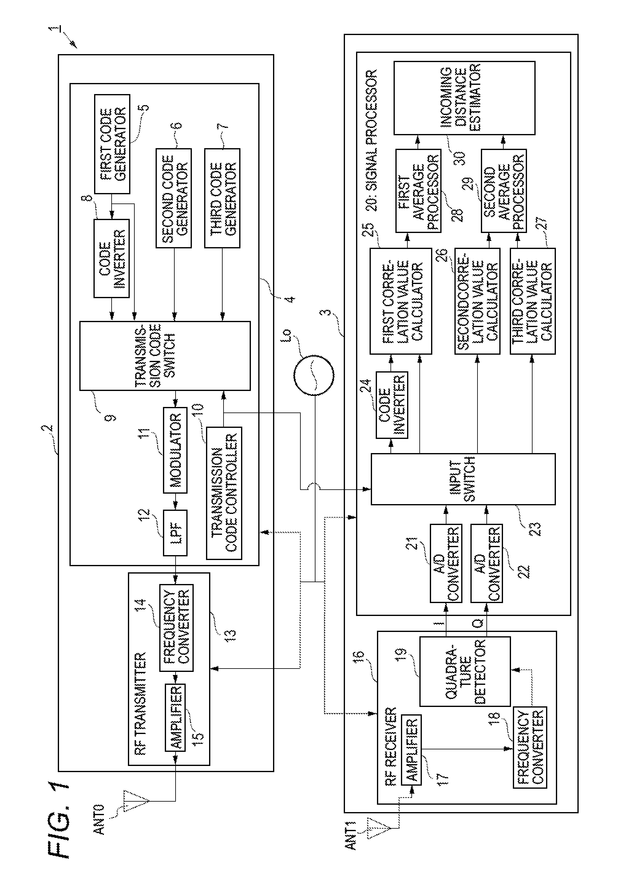
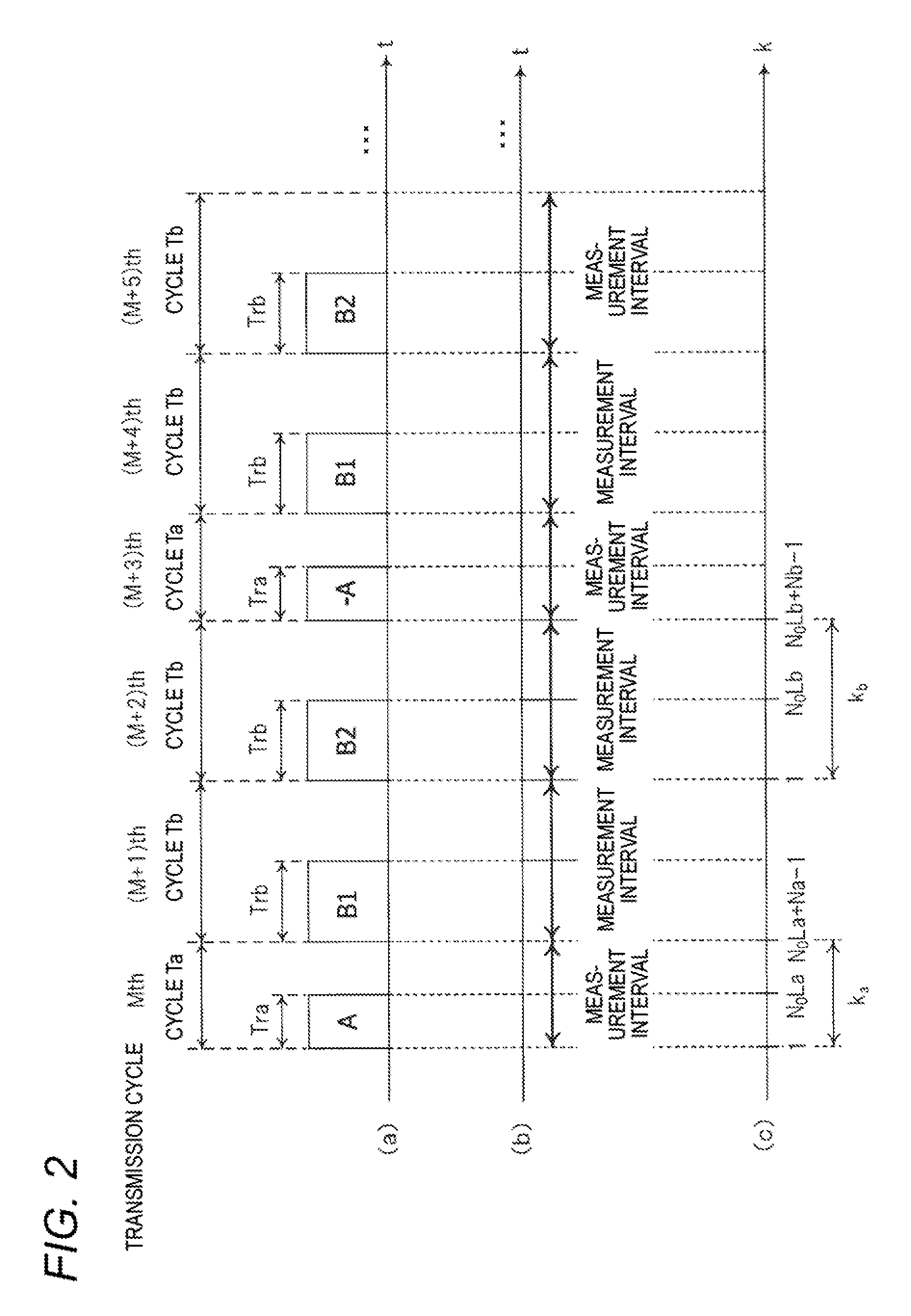
[0054]The configuration and operation of a radar apparatus 1 according to a first embodiment will be described with reference to FIGS. 1 and 2. FIG. 1 is a block diagram showing the internal configuration of the radar apparatus 1 according to the first embodiment. FIG. 2 is a timing chart illustrating how the radar apparatus 1 according to the first embodiment operates. In FIG. 2, (a) is an explanatory diagram showing transmission cycles Ta, transmission cycles Tb, and transmission codes used in the respective transmission cycles. In FIG. 2, (b) is an explanatory diagram showing measurement intervals. In FIG. 2, (c) is an explanatory diagram showing relationships between transmission cycles Ta and Tb and discrete times ka and kb, respectively.

[0055]As shown in FIG. 1, the radar apparatus 1 is configured so as to include a reference oscillator Lo, a radar transmitter 2 to which a transmission antenna ANT0 is connected, and a radar receiver 3 to which a reception antenna ANT1 is conne...

modification 1

of Embodiment 1

[0139]The first embodiment is directed to the case that the parameter Za which is an integer by which the transmission cycle Ta is to be multiplied and the parameters Zb1 and Zb2 which are integers by which the transmission cycle Tb is to be multiplied are all equal to 1. That is, the first embodiment is directed to the case that as shown in FIG. 2 the transmission code A is used in the Mth transmission cycle (transmission cycle Ta), the transmission code B1 is used in the (M+1)th transmission cycle (transmission cycle Tb), and the transmission code B2 is used in the (M+2)th transmission cycle (transmission cycle Tb).

[0140]A first modification of the first embodiment is directed to a case that each of the parameters Za, Zb1, and Zb2 is not equal to 1 but equal to a natural number that is larger than or equal to 2.

[0141]More specifically, after a high-frequency transmission signal generated according to the transmission code A is transmitted in an Mth transmission cycl...

embodiment 21

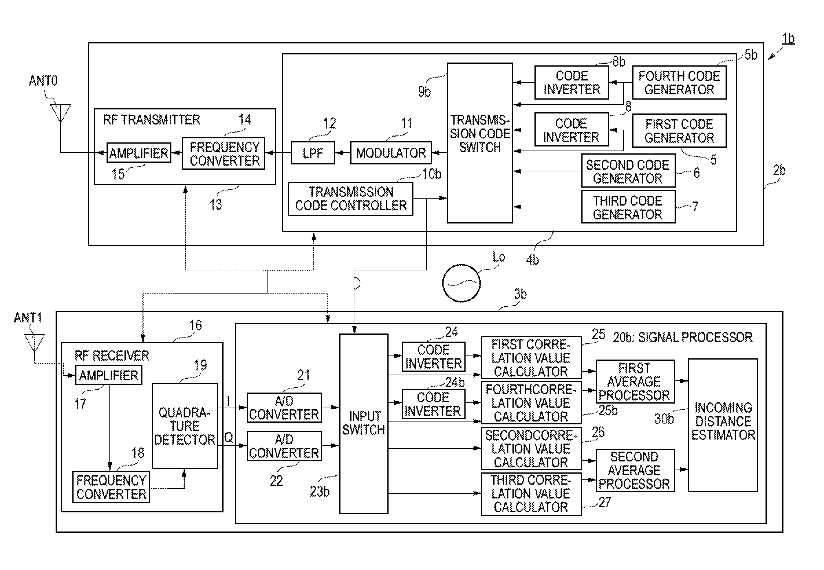
[0151]Next, the configuration and operation of a radar apparatus 1b according to a second embodiment will be described with reference to FIGS. 5 and 6. FIG. 5 is a block diagram showing the internal configuration of the radar apparatus 1B according to the second embodiment. FIG. 6 is a timing chart illustrating how the radar apparatus 1b according to the second embodiment operates. In FIG. 6, (a) is an explanatory diagram showing transmission cycles Ta, transmission cycles Tb, and transmission codes used in the respective transmission cycles. In FIG. 6, (b) is an explanatory diagram showing measurement intervals. In FIG. 6, (c) is an explanatory diagram showing relationships between transmission cycles Ta and Tb and discrete times ka and kb, respectively.

[0152]In the following description of the second embodiment, parts of the configuration and operation that are different than in the first embodiment will be described and the same parts of the configuration and operation as in the ...


PUM


Abstract

A radar apparatus transmits a high-frequency transmission signal, and receives a signal of a reflective wave reflected by a target. Given a first code sequence of a first code length, a second code sequence of a second code length which is longer than the first code sequence, and a third code sequence obtained by inverting each code of the first code sequence, a first transmission signal obtained by modulating the first code sequence, a second transmission signal obtained by modulating the second code sequence, a third transmission signal obtained by modulating the third code sequence and a fourth transmission signal obtained by modulating the second code sequence are generated in a first transmission period, a second transmission period, a third transmission period and a fourth transmission period respectively.

Description

BACKGROUND[0001]1. Technical Field[0002]The present invention relates to a radar apparatus which detects a target by receiving a signal of reflection waves reflected by the target with an antenna.[0003]2. Description of the Related Art[0004]Radar apparatuses are devices for measuring a distance between a target and a measuring place, a direction of the target from the measuring place, and other items by radiating radio waves to the space from the measuring place and receiving a signal of reflection waves reflected by the target. In particular, in recent years, radar apparatuses which can detect targets including not only automobiles but also pedestrians etc. by a high-resolution measurement using short-wavelength radio waves such as microwaves or millimeter waves have been being developed.[0005]There may occur a case that a radar apparatus receives a signal that is a mixture of reflection waves coming from a nearby target and reflection waves coming from a distant target. In particu...

Claims


Application Information

Patent Timeline
Patent Type & Authority Patents(United States)
IPC IPC(8): G01S13/28G01S13/00G01S13/93G01S13/931
CPCG01S13/284G01S13/931G01S13/288
Inventor KISHIGAMI, TAKAAKINAKAGAWA, YOICHIMUKAI, HIROHITO
Owner PANASONIC INTELLECTUAL PROPERTY MANAGEMENT CO LTD
Why Eureka
Try Eureka