Vibrating motor

A vibration motor and vibration direction technology, applied in the direction of electromechanical devices, electrical components, etc., can solve the problems that cannot meet the development trend of portable electronic equipment, the low utilization rate of the magnetic field of the vibration motor, and the large volume of the vibration motor, and achieve small thickness and high magnetic field utilization. High rate, performance-enhancing effect

Active Publication Date: 2016-05-04
GOERTEK INC
View PDF6 Cites 31 Cited by
  • Summary
  • Abstract
  • Description
  • Claims
  • Application Information

AI Technical Summary

Problems solved by technology

The magnetic field utilization rate of the vibration motor with this structure is low, and the vibration feeling is weak. It needs a large size of the coil and permanent magnet in the vertical direction to meet the design performance o

Method used


Image

  • Vibrating motor
  • Vibrating motor
  • Vibrating motor

Examples


Embodiment 1

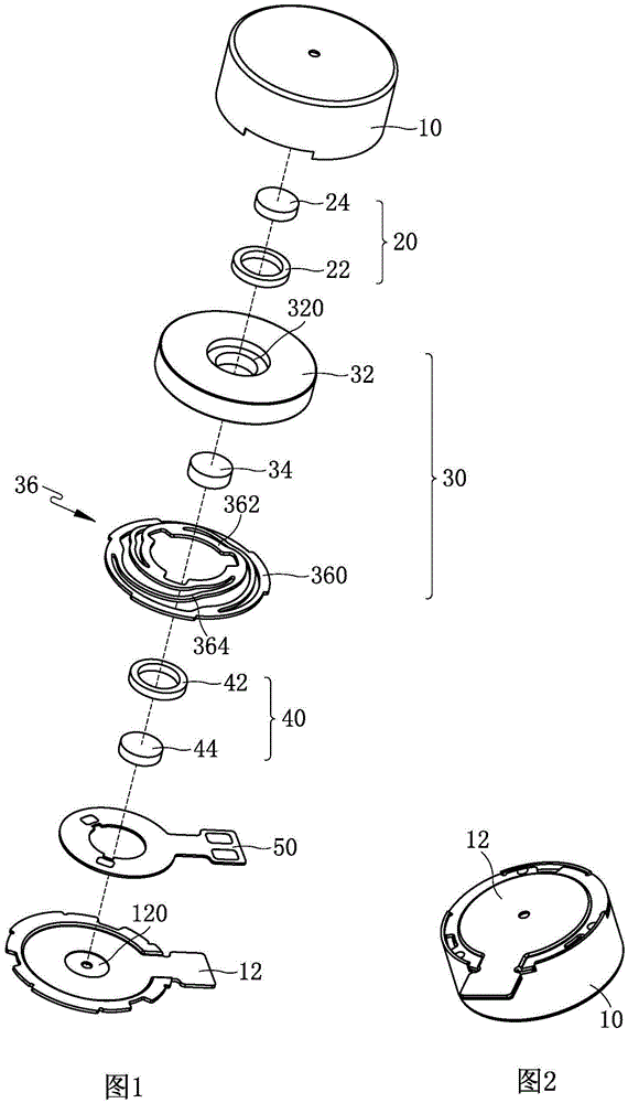
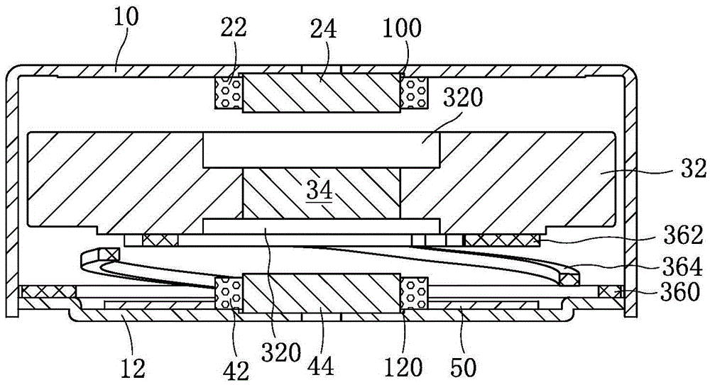
[0030] Such as figure 1 , figure 2 with image 3 As shown together, a vibration motor has a circular structure, including a housing, a stator, a vibrator 30 and an elastic support member 36 for supporting the vibrator 30 and providing elastic restoring force. The housing includes an upper shell 10 and a lower shell 12 combined together, the upper shell 10 is a box-like structure with one end open, the lower shell 12 is a plate-like structure, and the open end of the upper shell 10 is buckled on the lower shell 12 . In this embodiment, the stator includes a first stator 20 fixed on the upper shell 10 and a second stator 40 fixed on the lower shell 12, the elastic support member 36 is arranged between the vibrator 30 and the lower shell 12, and the vibrator 30 is elastically supported The member 36 is suspended in the space enclosed by the upper shell 10 and the lower shell 12 .

[0031] Such as figure 1 with image 3 Commonly shown, the vibrator 30 includes a circular ma...

Embodiment 2

[0036] This embodiment is basically the same as Embodiment 1, the difference is that:

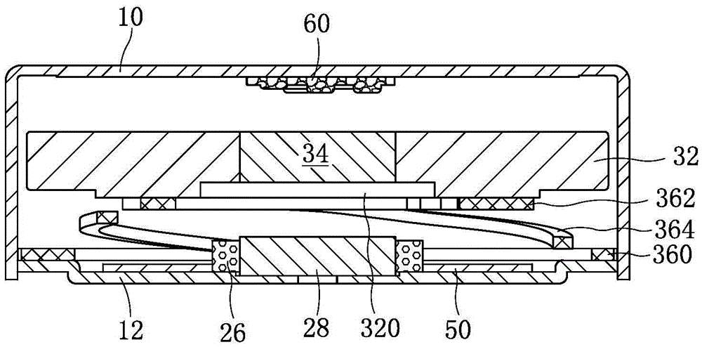
[0037] Such as Figure 4 As shown, the stator is only fixed on the inner side of the lower case 12, including the coil 26 and the iron core 28 arranged in the middle of the coil 26, the underside of the mass block 32 is provided with an escape portion 320 for avoiding the stator, and the lower surface of the permanent magnet 34 is lower than The lower surface of mass block 32. The upper surface of the permanent magnet 34 is flush with the upper surface of the mass block 32 , and the inner side of the upper shell 10 is provided with a foam 60 at a position corresponding to the permanent magnet 34 . The foam 60 is used to prevent noise from being generated when the vibrator collides with the upper case, and plays a protective role.

[0038] Compared with the first embodiment, the strength of the magnetic field in this embodiment is weakened, but the height of the vibration motor can be redu...

Embodiment 3

[0040] This embodiment is basically the same as Embodiment 1, the difference is that:

[0041] Such as Figure 5 As shown, the first stator only includes the first coil 22, the second stator only includes the second coil 42, the size of the permanent magnet 34 in the vibration direction is greater than the size of the mass block 32 in the vibration direction, that is, the upper part of the permanent magnet 34 Both the surface and the lower surface are higher than the upper surface and the lower surface of the mass block 32 . The diameter of the permanent magnet 34 is smaller than the diameter of the first coil 22 and the second coil 42. When the vibrator vibrates up and down, the space in the coil can also become the vibration space of the vibrator, which makes full use of the internal space of the vibration motor, which is beneficial to reduce the vibration. The thickness of the motor.

[0042] Compared with the first embodiment, the volume of the permanent magnet 34 in thi...


PUM


Abstract

The invention discloses a vibrating motor relating to the micro-motor technical field. The vibrating motor comprises a shell body, a stator and a vibrator; the vibrator is suspended in the shell body through an elastic supporting element; the vibrator comprises a quality block and a permanent magnet embedded on the quality block; the stator comprises a coil; the coil is a disc coil, is horizontally fixed on the shell body and corresponds to the permanent magnet in the vertical direction; the magnetizing direction of the permanent magnet is parallel to the magnetic field direction generated by the coil; and a vibrating space is reserved between the vibrator and the stator on in a vibration direction. According to the vibrating motor of the invention, the technical problems that the vibrating motor in the prior art is large in thickness and small in vibrating sense are solved; the vibrating motor of the invention is featured by strong vibrating sense, small thickness, high reliability and long service life and can satisfy the design demands of a portable charging device for high performance and thin type of the vibrating motor.

Description

technical field [0001] The invention relates to the technical field of micro motors, in particular to a Z-direction vibration motor. Background technique [0002] Z-direction vibration motor is a kind of micro motor, its vibration direction is vertical, and it is mostly used in portable electronic products, such as mobile phones, handheld game consoles and handheld multimedia entertainment equipment. The vibration motor usually includes a housing, a stator and a vibrator. The stator includes a coil fixed on the housing. The vibrator includes a permanent magnet corresponding to the coil in the vertical direction and a mass block fixed with the permanent magnet. The vibrator passes through an elastic support. Suspended within the housing. [0003] The coils of the existing motors vibrating in the vertical direction are all cylindrical structures. The vibrator includes a pot frame, a permanent magnet and a mass block. There is a magnetic gap between the pot frame and the perma...

Claims


Application Information

Patent Timeline
IPC IPC(8): H02K33/00
CPCH02K33/00
Inventor 王超朱跃光
Owner GOERTEK INC
Why Eureka
Try Eureka