Adjustable non-Newtonian fluid deceleration strip

A technology of non-Newtonian fluids and speed bumps, which is applied to roads, road signs, traffic signals, etc., can solve the problems of lack of adjustment mechanisms, and achieve the effect of avoiding damage and improving the vibration feeling

Inactive Publication Date: 2021-07-27
莫立峰
View PDF6 Cites 0 Cited by
  • Summary
  • Abstract
  • Description
  • Claims
  • Application Information

AI Technical Summary

Problems solved by technology

[0003] The existing non-Newtonian fluid speed bumps lack an adjustment mechanism when they are in use, and the height of the speed bumps cannot be adjusted after installation. If the driver still does not take the initiative to slow down, he can still pass the speed bump at a faster speed. The shock to the driver is also within an acceptable range, so a new type of speed reduction belt is needed, so that the driver has to slow down and improve the speed reduction effect on the vehicle

Method used


Image

  • Adjustable non-Newtonian fluid deceleration strip
  • Adjustable non-Newtonian fluid deceleration strip
  • Adjustable non-Newtonian fluid deceleration strip

Examples


Embodiment 1

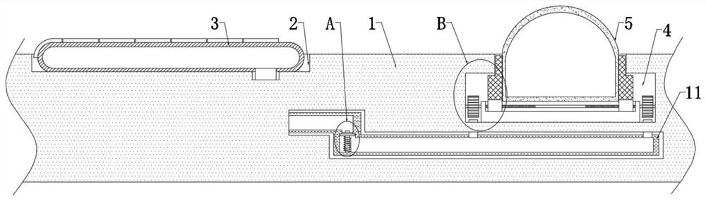
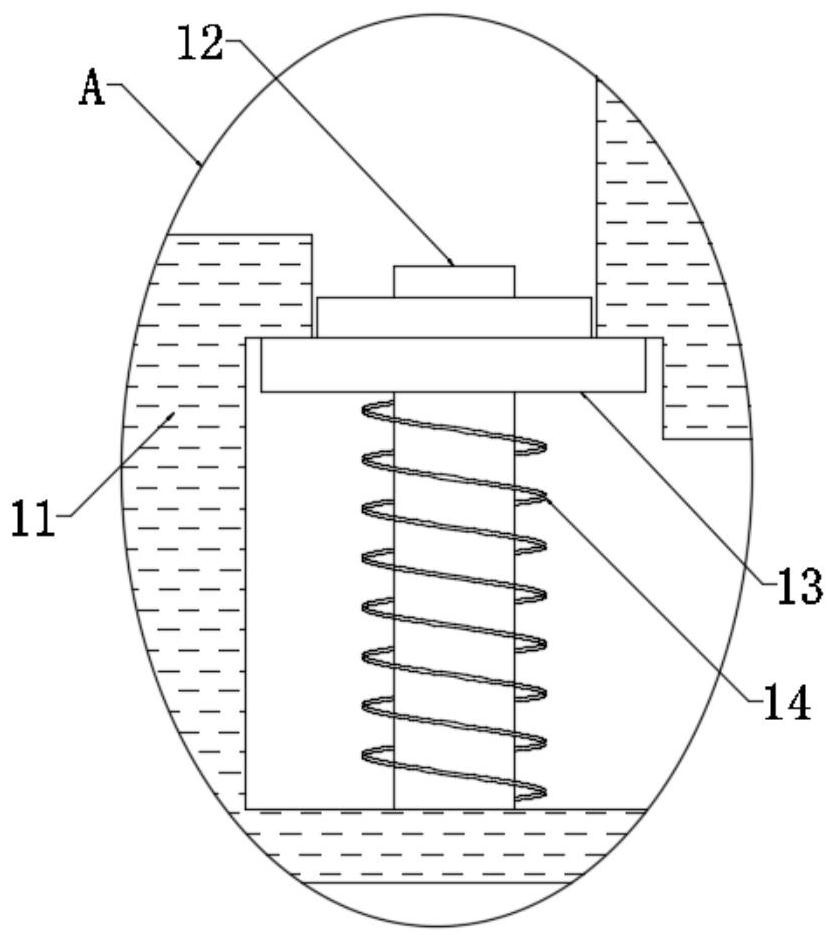
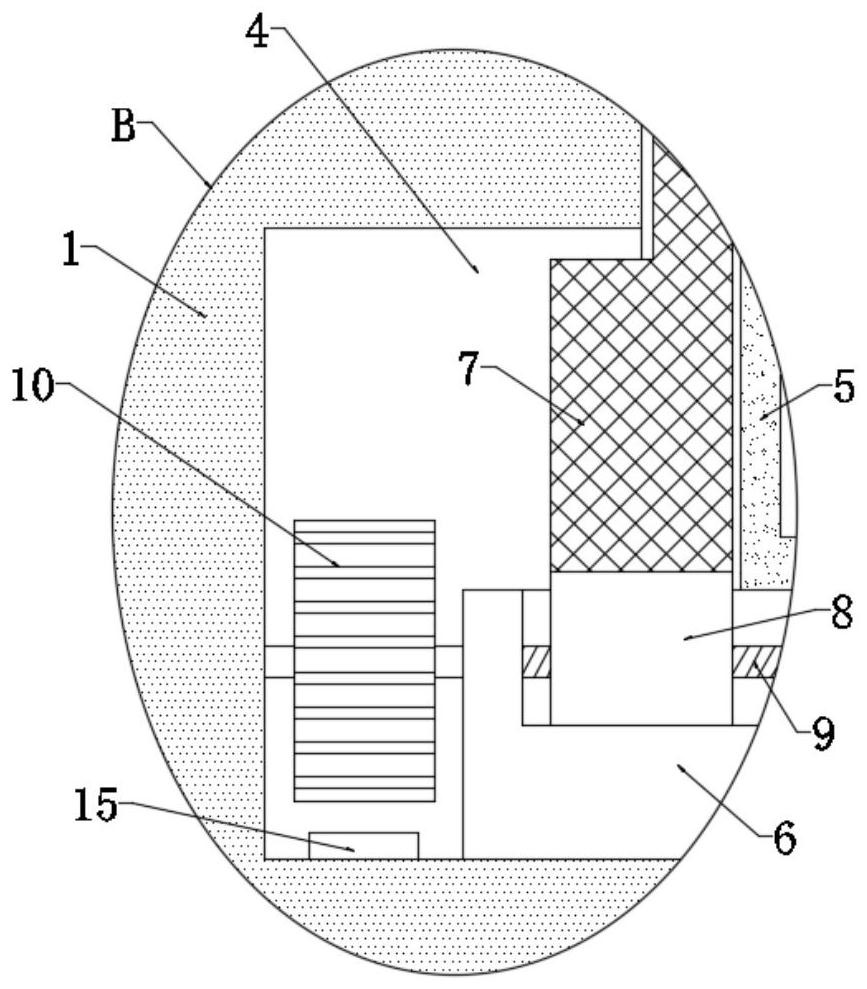
[0030] refer to Figure 1-3 , an adjustable non-Newtonian fluid speed bump, including a plurality of grooves 2 and a device groove 4 arranged on the upper end of the roadbed 1, the plurality of grooves 2 and the device groove 4 are misplaced, and the inside of the groove 2 is provided with a flat The elastic airbag 3, the upper surface of the elastic airbag 3 is evenly laid with a plurality of pressure plates, all of which are flexibly connected, and the interior of the subgrade 1 is also provided with a Z-shaped air guide tube 11, and the diameter of the Z-shaped air guide tube 11 is large enough , can allow a large amount of gas to pass through quickly, one end of the Z-shaped air duct 11 is connected with one end of the elastic air bag 3, the inside of the device tank 4 is provided with a bottom plate 6, and the bottom sides of the device tank 4 are respectively provided with nozzles 15, Z The other end of the type air duct 11 communicates with two nozzles 15, and the upper...

Embodiment 2

[0036] refer to Figure 4-5 , the present embodiment is different from Embodiment 1 in that: the interior of the subgrade 1 is also provided with an oblique air guide pipe 16, one end of the oblique air guide pipe 16 communicates with the Z-shaped air guide pipe 11, and the other end of the oblique air guide pipe 16 Connected with the next elastic airbag 3, the inside of the oblique air guide tube 16 is provided with a one-way valve 17, the gas flowing out from the previous Z-shaped air guide tube 11 will be stored inside the next elastic air bag 3, and the one-way valve 17 can avoid The gas flows back, thereby increasing the gas storage capacity inside the next elastic airbag 3 .

[0037]The working principle of this embodiment: if the vehicle passes through multiple non-Newtonian fluid speed bump bodies 5 at a faster speed and has no intention of decelerating, the gas part inside the previous elastic airbag 3 flows into the oblique air duct 16 through the Z-shaped air duct 1...


PUM


Abstract

The invention discloses an adjustable non-Newtonian fluid deceleration strip which comprises a plurality of grooves and device grooves which are formed in the upper end of a roadbed, the grooves and the device grooves are arranged in a staggered mode, flat elastic air bags are arranged in the grooves, and a plurality of pressing plates are evenly laid on the upper surfaces of the elastic air bags. The multiple pressing plates are movably connected, a Z-shaped air guide pipe is further arranged in the roadbed, one end of the Z-shaped air guide pipe communicates with one end of the elastic air bag, a bottom plate is arranged in the device groove, and spray heads are arranged on the two sides of the bottom of the device groove correspondingly. The non-Newtonian fluid deceleration strip is reasonable in structure, the height of the non-Newtonian fluid speed bump bodies can be increased, the vibration sense of a vehicle during vibration is improved, and if the vehicle passes through the multiple non-Newtonian fluid speed bump bodies at a high speed and does not have the speed reduction intention, the stronger and stronger vibration sense can be brought to the vehicle, and the vehicle is forced to be driven at a reduced speed.

Description

technical field [0001] The invention relates to the technical field of speed bumps, in particular to an adjustable non-Newtonian fluid speed bump. Background technique [0002] The speed bump is a kind of traffic safety facility. It is a barrier with slopes on both sides and slightly higher than the road surface. It is usually set on roads prone to traffic accidents or roads that require vehicles to slow down. It can also be installed in schools, residential areas and The entrance of industrial and mining enterprises. Non-Newtonian fluids refer to fluids that do not satisfy Newton’s viscosity experimental law, that is, fluids whose shear stress and shear strain rate are not linearly related. At present, there are also non-Newtonian liquid speed bumps. When a car slowly passes through non-Newtonian fluids When the belt is belted, the speed reduction belt will be deformed, which will not bring severe bumps to the passing vehicles. When the vehicle passes through the non-Newto...

Claims


Application Information

Patent Timeline
Patent Type & Authority Applications(China)
IPC IPC(8): E01F9/529
CPCE01F9/529
Inventor 莫立峰
Owner 莫立峰
Why Eureka
Try Eureka