Laser welding method

一种激光焊接、激光的技术,应用在激光焊接设备、焊接设备、焊接/焊接/切割物品等方向,能够解决熔合不良等问题,达到抑制烧穿的效果

Active Publication Date: 2016-05-04
PANASONIC INTPROP MANAGEMENT CO LTD
View PDF11 Cites 27 Cited by
  • Summary
  • Abstract
  • Description
  • Claims
  • Application Information

AI Technical Summary

Problems solved by technology

If the accuracy of the irradiated part of the laser beam in the workpiece is poor, fusion failure due to misalignment of the laser beam is likely to occur

Method used


Image

  • Laser welding method
  • Laser welding method
  • Laser welding method

Examples


Embodiment approach 1

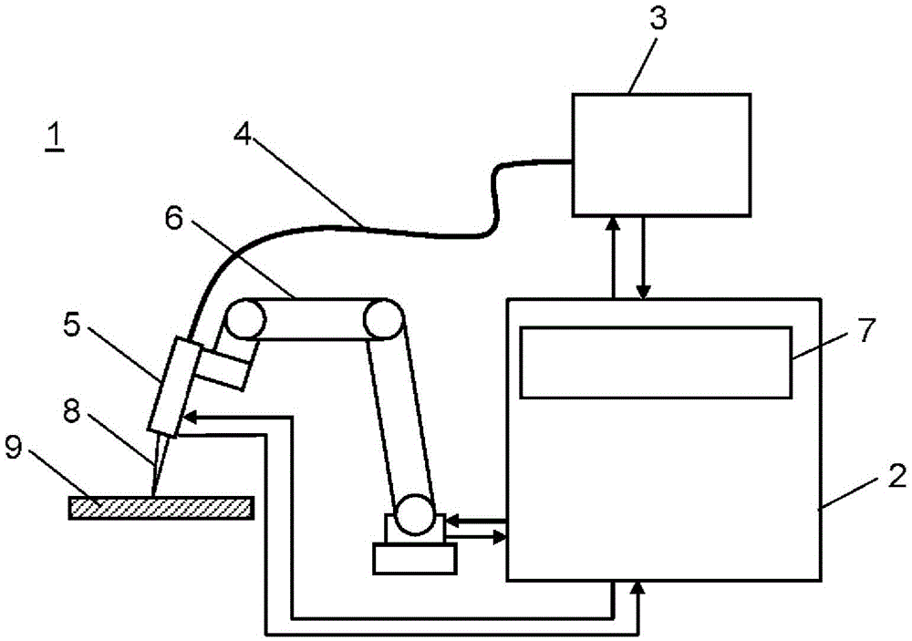
[0040] use figure 1 The structure of the laser welding apparatus in this embodiment is demonstrated. figure 1 It is a figure which shows the schematic structure of the laser welding apparatus 1 in this embodiment.

[0041] exist figure 1 Among them, a laser welding device 1 has a control unit 2 , a laser oscillator 3 , an optical fiber 4 , a laser irradiation head 5 , and a manipulator 6 .

[0042] In the laser welding device 1 , the controller 2 is connected to the laser oscillator 3 , the laser irradiation head 5 , and the manipulator 6 to control the operations of the laser oscillator 3 , the laser irradiation head 5 , and the manipulator 6 . In addition, the control part 2 has the output switching part 7 which switches the energy of the laser light output from the laser oscillator 3. Laser oscillator 3 outputs laser light 8 based on an instruction from control unit 2 . The optical fiber 4 is connected to the laser oscillator 3 and the laser irradiation head 5 , and tra...

Embodiment approach 2

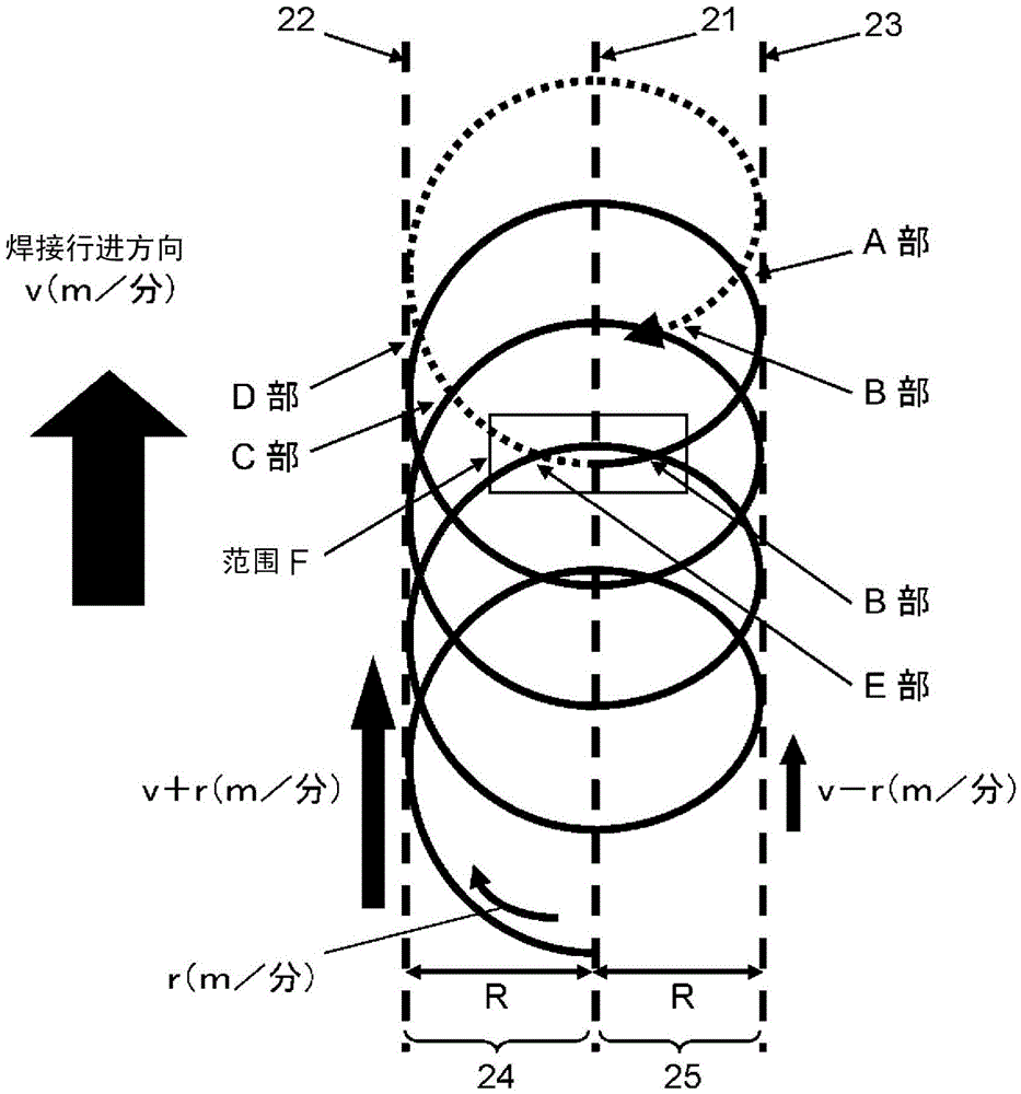
[0075] Next, use Figure 12 to Figure 20 Embodiment 2 of the present disclosure will be described. In this embodiment, the same parts as in Embodiment 1 are given the same reference numerals, and detailed description thereof will be omitted. The difference from Embodiment 1 is that the energy of the laser light in the front-back direction of the welding advancing direction is further taken into consideration.

[0076] In Embodiment 1, the laser welding method in which the heat input by irradiation of the laser beam is symmetrical in the left-right direction with respect to the welding progress direction was described. In the present embodiment, the amount of heat input by irradiation of laser light in the front-rear direction of the welding proceeding direction is controlled. This does not mean that the heat input by laser irradiation must be symmetrical in the front-back direction of the welding advancing direction, but requires an optimal heat input balance in the front-ba...

Embodiment approach 3

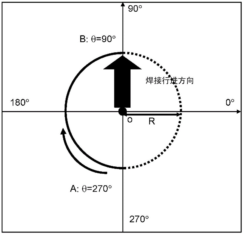
[0083] Next, use Figure 22 Embodiment 3 of the present disclosure will be described. In this embodiment, the same parts as in Embodiment 1 are given the same reference numerals, and detailed description thereof will be omitted. The difference from Embodiment 1 is that, similarly to Embodiment 2, the energy of the laser light in the front-back direction of the welding advancing direction is also taken into consideration. Also, the difference from Embodiment 2 is that the total amount of laser energy applied to the rear in the welding advancing direction is larger than the total amount of laser energy applied to the front in the welding advancing direction. In this embodiment, similarly to Embodiment 2, it is not necessary to make the heat input by irradiation of the laser beam symmetrical in the front-back direction of the welding advancing direction, but requires an optimal balance of heat input in the front-back direction.

[0084] When the workpiece 9 is, for example, a g...


PUM


Abstract

The invention provides a laser welding method. The laser welding method according to the present disclosure has a step for emitting laser light in a spiral shape along the welding site on a workpiece. The spiral shape is obtained by combining a circular path, in which a laser beam is moved in a circular shape, and a moving path, in which the laser beam is moved in the advancing direction along the welding site. First energy of the laser beam moving in the circular path so as to have an advancing-direction component is greater than second energy of the laser beam moving in the circular path so as to have a component in the direction opposite the advancing direction.

Description

technical field [0001] The present invention relates to a laser welding method for irradiating a laser beam to a workpiece while scanning the laser beam in a helical shape. Background technique [0002] In laser welding, laser light is irradiated to the joining portion of two workpieces to be joined, and the workpieces at the irradiated portion are melted and joined by the energy of the laser light. Laser welding can perform high-speed welding because it does not come into physical contact with the workpiece. In addition, since laser welding has a high energy density of laser light, it is possible to perform welding while limiting the influence of heat to a narrow range of the workpiece. [0003] On the other hand, in laser welding, the width of the bead to be welded is narrow. Therefore, the margin of misalignment of the aiming of the laser light is narrow, and the accuracy of the irradiated portion of the laser light in the workpiece is required. When the accuracy of th...

Claims


Application Information

Patent Timeline
Patent Type & Authority Applications(China)
IPC IPC(8): B23K26/08B23K26/21B23K26/322
CPCB23K26/0626B23K26/082B23K26/0876B23K26/24B23K2101/34B23K2101/35B23K2103/04B23K2103/08B23K26/322
Inventor 松冈范幸向井康士川本笃宽藤原润司中川龙幸
Owner PANASONIC INTPROP MANAGEMENT CO LTD
Why Eureka
Try Eureka