
Upper discharge device of filtering tank

A drainage device and filter tank technology, applied in the feed/discharge device of the settling tank, chemical instruments and methods, separation methods, etc., can solve the problems of sedimentation, long time-consuming filtration, and reduced efficiency of solid-liquid separation

Inactive Publication Date: 2016-05-11
秦桂芳
View PDF6 Cites 8 Cited by
  • Summary
  • Abstract
  • Description
  • Claims
  • Application Information

AI Technical Summary

Problems solved by technology

[0002] In today's chemical and environmental protection fields, many sedimentation and filtration equipment and devices are used, especially when solid-liquid separation is required, and the solid matter has a low water content. The water content of the solid matter after precipitation treatment is still very high. High, further filtration or dehydration treatment is still required, usually the liquid to be filtered is filtered through the filter at the bottom and then discharged, making the entire precipitation and filtration time-consuming, and the efficiency of solid-liquid separation is greatly reduced

Method used


Image

  • Upper discharge device of filtering tank
  • Upper discharge device of filtering tank
  • Upper discharge device of filtering tank

Examples


Embodiment 1

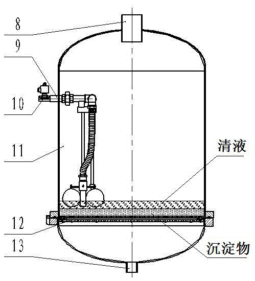
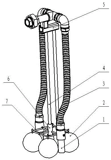
[0014] Embodiment 1: A drainage device on a filter tank, including a float, a connecting frame, a suction nozzle, a hose, a valve, and a tank body. The tank body is a closed container, and the floating ball, the connecting frame, the suction nozzle, and the hose are Set inside the tank, there are four floating balls fixed on the connecting frame and floating on the liquid surface, the suction nozzle is fixed on the connecting frame, one end of the suction nozzle is inserted into the liquid surface, and the other end is connected to the drain on the upper part of the tank through a hose The outlet is connected, a valve is installed at the drain, the guide rod that is placed vertically and passes through the guide ring is fixedly connected with the guide rod frame, the guide rod frame is fixed on the inner wall of the tank, and the guide ring is fixed on the connecting frame, so that Make the float and the connecting frame move up and down along the guide rod with the height of t...

Embodiment 2

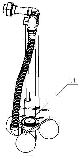
[0016] Embodiment 2: A drainage device on a filter tank, including a float, a connecting frame, a hose, a submersible pump, and a tank body. The tank body is a closed container, and the float ball, connecting frame, submersible pump, and hose are all arranged on Inside the tank, there are three floating balls fixed on the connecting frame and floating on the liquid surface. The submersible pump is fixed on the connecting frame. The suction end of the submersible pump is located below the liquid surface. The drain port of the tank is connected, the guide rod that is placed vertically and passes through the guide ring is fixedly connected with the guide rod frame, the guide rod frame is fixed on the inner wall of the tank, and the guide ring is fixed on the connecting frame, so that the floating ball and the connection The frame moves up and down along the guide rod with the height of the liquid level.

[0017] The liquid to be filtered is injected from the feed port of the tank...


PUM


Abstract

The invention discloses an upper discharge device of a filtering tank, which comprises floating balls, a connection rack, a suction nozzle, a hose, a valve and a tank body, wherein the tank body is a closed container, the floating balls, the connection rack, the suction nozzle and the hose are arranged inside the tank body, at least three floating balls are fixed on the connection rack and float on the liquid surface, the suction nozzle is fixed on the connection rack, one end of the suction nozzle is inserted into the liquid surface, and the other end of the suction nozzle is communicated with a water discharge port on the upper part of the tank body through the hose. According to the filtering equipment and device applied to the fields of chemical industry and environment protection, after filtered liquid is settled, the clear liquid on the upper part is discharged by the upper discharge device, and residue and water separation is rapidly realized, so that the filtering efficiency is greatly improved.

Description

technical field [0001] The invention relates to the fields of chemical industry and environmental protection, in particular to an upper drainage device for a filter tank. Background technique [0002] In today's chemical and environmental protection fields, many sedimentation and filtration equipment and devices are used, especially when solid-liquid separation is required, and the solid matter has a low water content. The water content of the solid matter after precipitation treatment is still very high. High, further filtration or dehydration treatment is still required. Usually, the liquid to be filtered is filtered through the filter at the bottom and discharged, which makes the entire precipitation and filtration time-consuming and the efficiency of solid-liquid separation is greatly reduced. Contents of the invention [0003] In view of the deficiencies in the prior art, the present invention proposes a set of solutions for simultaneous sedimentation and filtration, ...

Claims


Application Information

Patent Timeline
Patent Type & Authority Applications(China)
IPC IPC(8): B01D21/24
CPCB01D21/2444B01D21/245
Inventor 不公告发明人
Owner 秦桂芳
Learn More