
Numerical control multi-position die changing mechanism

A technology of rotating mechanism and mold base, which is applied in the direction of metal processing equipment, forming tools, manufacturing tools, etc., can solve the problems of increased cost, long time-consuming, cumbersome bending process, etc., to facilitate disassembly and maintenance, improve production efficiency, and save space The effect of less interference

Active Publication Date: 2016-05-11
FOSHAN TIANJIAN MECHANICAL CO LTD
View PDF10 Cites 4 Cited by
  • Summary
  • Abstract
  • Description
  • Claims
  • Application Information

AI Technical Summary

Problems solved by technology

For copper pipes that need to be bent in different directions multiple times, using the existing bending machine 000' will make the entire bending process too cumbersome, time-consuming, and the quality of the bending cannot be effectively guaranteed. In addition, the entire bending The structure of the shape machine 000' is also too complicated, with a lot of space interference
[0005] In addition, copper pipes with different pipe diameters also need to use different R molds for pipe bending operations. If copper pipes with different pipe diameters are used for pipe bending operations on the same pipe bender, it is necessary to replace the corresponding R mold for the diameter of the copper pipe. It takes a long time and low efficiency; if multiple sets of pipe bending machines are used to bend copper pipes with different diameters, the cost will be greatly increased

Method used


Image

  • Numerical control multi-position die changing mechanism
  • Numerical control multi-position die changing mechanism
  • Numerical control multi-position die changing mechanism

Examples


Embodiment Construction

[0023] The technical solutions claimed in the present invention will be further described in detail in conjunction with the accompanying drawings and specific embodiments.

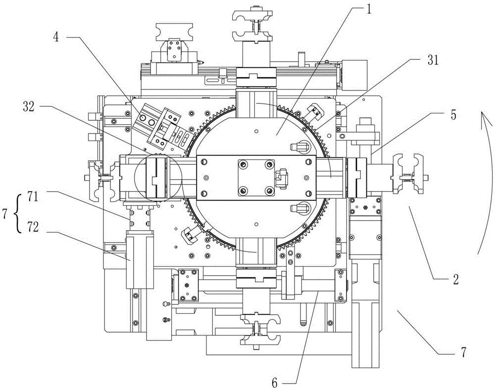
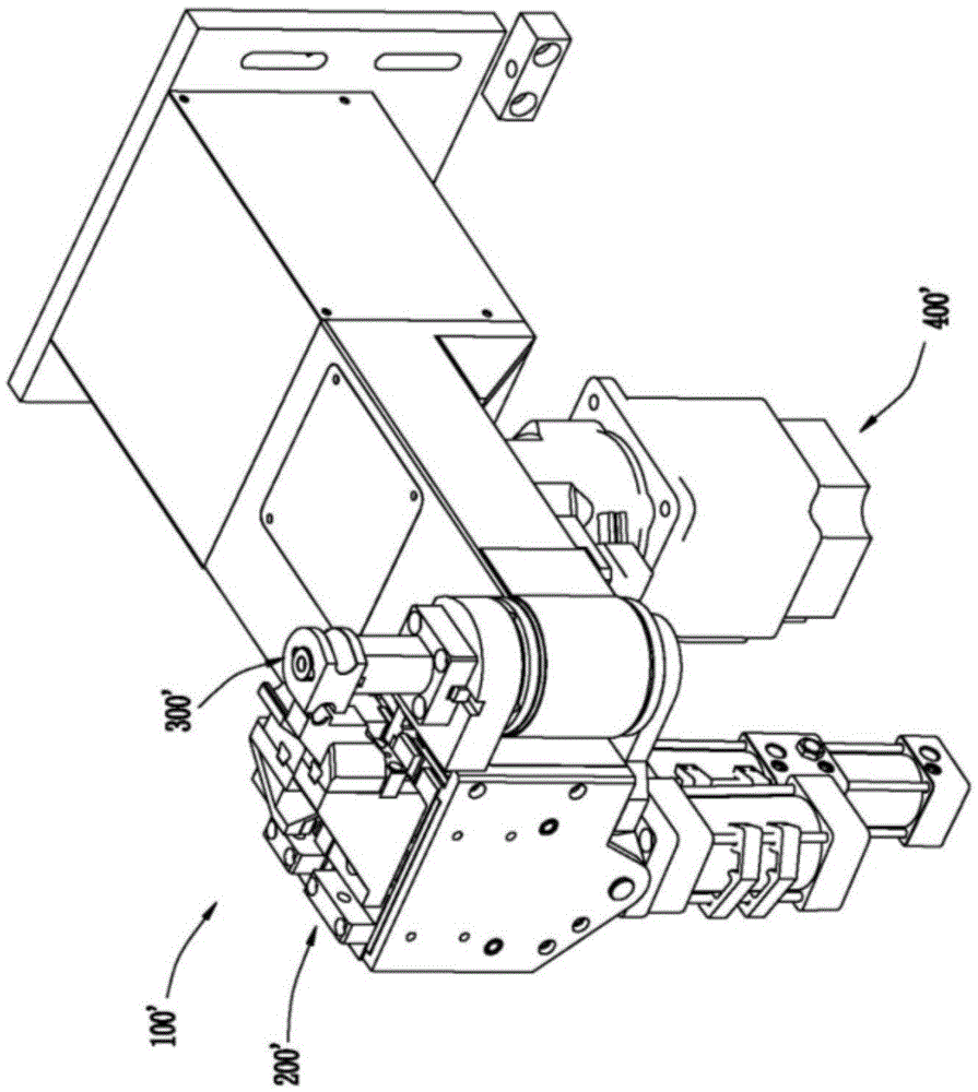
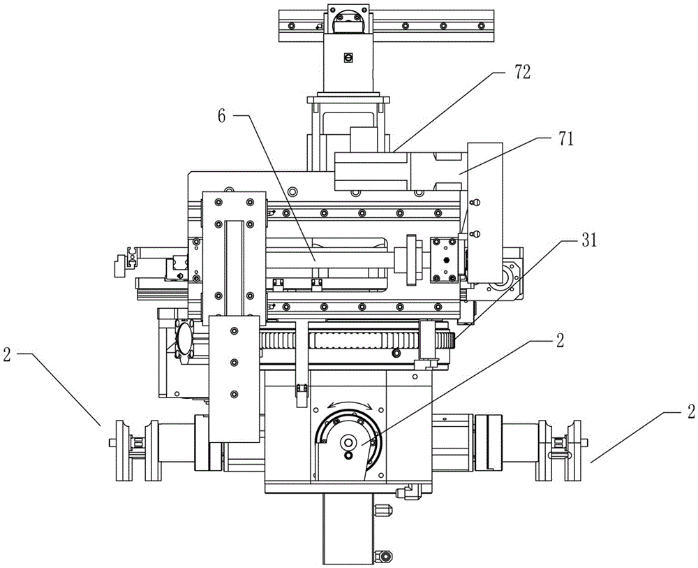
[0024] See attached figure 2 to attach Figure 5 As shown, a numerically controlled multi-position mold changing mechanism of the present invention includes a headstock 1, a rotating mechanism for driving the headstock 1 to rotate at a set angle, and a lock for locking the headstock 1. Tightening mechanism 4, the machine head lifting mechanism for driving the machine head base 1 to lift and the translation mechanism for driving the machine head base 1 to translate.

[0025] The headstock 1 is provided with a built-in driving gear 11 whose axis of rotation coincides with the rotating shaft of the headstock 1, is used to drive the drive unit 7 for driving the driving gear 11 to rotate, and the drive cylinder 12 whose piston rod coincides with the rotating shaft of the headstock 1 is connected to The wedge...


PUM


Abstract

The invention discloses a numerical control multi-position die changing mechanism, which comprises a headstock and a headstock rotating mechanism used for driving the headstock to rotate at a set angle; a rotating shaft axis, a driving gear, a driving unit, a driving oil cylinder and a tapered wedge are arranged in the headstock, wherein the driving gear is superposed with a rotating shaft of the headstock, the driving unit is used for driving the driving gear to rotate, a piston rod of the driving oil cylinder is superposed with the rotating shaft of the headstock, and the tapered wedge is connected with the tail end of the piston rod of the driving oil cylinder; the numerical control multi-position die changing mechanism also comprises multiple groups of R die assemblies annularly distributed around the rotating shaft axis of the headstock; each R die assembly comprises an upper die, a lower die, an R die mounting base, a bearing, a bearing mounting base, a driven gear and a double-section pull rod, wherein the bearing is used for driving the R die mounting base to rotate, the bearing mounting base is used for connecting the headstock with the bearing, a rotating shaft axis of the driven gear is perpendicular to the rotating shaft of the headstock, and the double-section pull rod extends along a direction perpendicular to the rotating shaft of the headstock to the interior of the headstock.

Description

technical field [0001] The invention relates to the technical field of pipe bending equipment, in particular to a numerically controlled multi-position die changing mechanism. Background technique [0002] In the refrigeration industry, refrigeration copper tubes are a common refrigeration accessory, mainly used for the circulation of refrigerant; Installation arrangement. When the existing copper pipe is bent, it is generally bent by a bending machine with a steering mechanism for turning the copper pipe and can only be bent in one direction, and The bending radius generally does not exceed two. If it is necessary to bend pipes in different directions and different bending radii in succession, it is necessary to replace different bending machines several times. [0003] See attached figure 1 Shown is a schematic structural view of the existing one-way bending machine 000' (where the steering mechanism on the existing one-way bending machine is not shown), the existing o...

Claims


Application Information

Patent Timeline
IPC IPC(8): B21D7/08B21D37/04
CPCB21D7/085B21D37/04
Inventor 黄伟明
Owner FOSHAN TIANJIAN MECHANICAL CO LTD
Features
  • Generate Ideas
  • Intellectual Property
  • Life Sciences
  • Materials
  • Tech Scout
  • Unparalleled Data Quality
  • Higher Quality Content
  • 60% Fewer Hallucinations
Learn More