Buffering type sterilizing and light-emitting cutting tool high in bonding strength

A combination of strength and cutting tool technology, applied in the field of cutting tools, can solve the problems of insufficient bonding strength between the blade and the tool body, poor strength and wear resistance, shortened service life of the blade, etc., to achieve high wear capacity, high strength and wear resistance Performance and service life extension effect

Inactive Publication Date: 2016-05-11
倪传华
View PDF4 Cites 0 Cited by
  • Summary
  • Abstract
  • Description
  • Claims
  • Application Information

AI Technical Summary

Problems solved by technology

[0002] At present, the blades of cutting tools are made of high-speed steel materials, but the strength and wear resistance of high-speed steel materials are poor, which makes cutting tools very easy to damage during use, which increases the burden on enterprises and brings greater losses to enterprises.
At the same time, when the cutting tool is cutting steel, due to the diffusion reaction between the tool and the chip at the cutting temperature, the cutting tool is very prone to crater wear, which further reduces the service life
At the same time, the impact of the current punch is relatively large, and the blade is easily damaged during the stamping process, which greatly shortens the service life of the blade and brings unnecessary losses to the enterprise. In addition, the bonding strength between the blade and the tool body is not enough, which often easily causes the blade to break. damage, which brought great losses to the enterprise
At the same time, the overall quality of the current blade is relatively large, which affects the use of the tool, and is made of tungsten-titanium-cobalt cemented carbide, and the cost is also high
In addition, the impact of the current punch is relatively large, and the blade is easily damaged during the stamping process, which greatly shortens the service life of the blade and brings unnecessary losses to the enterprise.

Method used


Image

  • Buffering type sterilizing and light-emitting cutting tool high in bonding strength

Examples


Embodiment Construction

[0013] The present invention will be further described below in conjunction with the accompanying drawings.

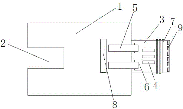
[0014] Such as figure 1 As shown, a buffer type sterilizing luminescent cutting tool with high bonding strength includes a tool body 1 and a blade 3, and a threaded hole 2 for connecting with a driving device is provided at the rear end of the tool body 1, and a threaded hole 2 is provided in the threaded hole There is an internal thread, and a blade 3 is arranged at the front end of the cutter body 1, and the blade 3 is made of tungsten-titanium-cobalt cemented carbide. The blade is made of YT05 / YT30 tungsten-titanium-cobalt cemented carbide. Three weight-reducing grooves 4 are arranged in the middle of the blade 3 , and the arrangement direction of the weight-reducing grooves 4 is perpendicular to the direction of the edge of the blade 3 . Two straps 5 are welded on the tool body 1, hooks are provided at the free ends of the straps 5, and two slots 6 are arranged a...


PUM


Abstract

The invention discloses a buffering type sterilizing and light-emitting cutting tool high in bonding strength. The buffering type sterilizing and light-emitting cutting tool is characterized by comprising a blade and overlapping sheets; a threaded hole used for being connected to a drive device is formed in the rear end of a cutting tool body, and internal threads are formed in the threaded hole; the blade is arranged at the front end of the cutting tool body, and a plurality of lightening grooves are formed in the middle of the blade; the two overlapping sheets are welded to the cutting tool body, hooks are arranged at the free ends of the overlapping sheets, two open grooves are formed in the rear end of the blade, and the hooks of the overlapping sheets can extend into the corresponding open grooves of the blade for matched connection; the cutting tool body is provided with a light source, light generated by the light source is ultraviolet light, the blade is provided with a plurality of light guide sheets, the light source and the light guide sheets are located on the same straight line, and the light guide sheets are perpendicular to a cutting edge, absorb the light emitted by the light source and guide the light to the cutting edge; three or more buffering mats are arranged at the part, extending out of an opening, of the blade in a sleeving mode, and the distance between every two adjacent buffering mats is equal.

Description

technical field [0001] The invention relates to a cutting tool, in particular to a buffer type sterilizing and luminescent cutting tool with high bonding strength. Background technique [0002] At present, the blades of cutting tools are made of high-speed steel materials, but the strength and wear resistance of high-speed steel materials are poor, which makes cutting tools very easy to damage during use, which increases the burden on enterprises and brings greater losses to enterprises. . At the same time, when the cutting tool is cutting steel, due to the diffusion reaction between the tool and the chips at the cutting temperature, the cutting tool is very prone to crater wear, which further reduces the service life. At the same time, the impact of the current punch is relatively large, and the blade is easily damaged during the stamping process, which greatly shortens the service life of the blade and brings unnecessary losses to the enterprise. In addition, the bonding ...

Claims


Application Information

Patent Timeline
Patent Type & Authority Applications(China)
IPC IPC(8): B21D37/10B21D37/01A61L2/10
CPCA61L2/10A61L2202/11B21D37/01B21D37/10
Inventor 倪传华
Owner 倪传华
Why Eureka
Try Eureka